Kenco Engineering KUSO Switch User Manual
Page 2
Wiring
It is recommended that conduit be installed onto the ¾” NPT connection on the back of the sensor. A seal drain fitting
should be used to prevent moisture from entering the switch. All wiring, conduit, and electrical fittings must conform to
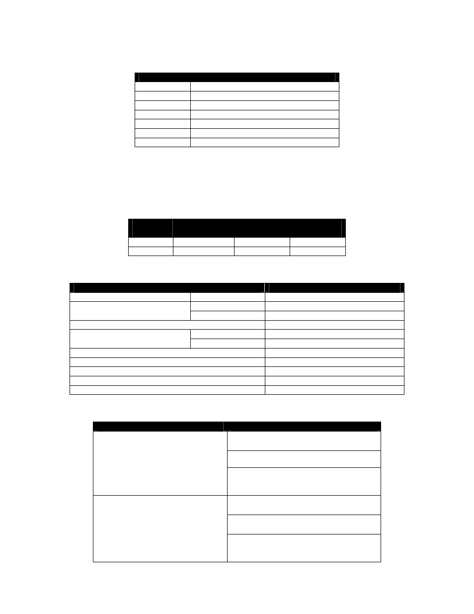
local electrical codes for the location selected. The wiring color code is shown in the following table:
Color
Function
Blue
Normally Open Contact (Relay version)
White
Common Contact (Relay version)
Brown
Normally Closed Contact (Relay version)
Black Power
(-)
Red Power
(+)
Green Ground
Silver (Bare)
Shield
Connect the Black and Red wires to the power source (6 – 24Vdc). If this is the 2-wire loop version, measure the current
in the red wire to determine the output condition (4.0mA ± 1.0mA = Dry; 16.0mA ± 1.0mA = Wet). For the Relay version,
you must also connect the Blue (NO), White (C), and Brown (NC) wires. The Green and Silver (Bare) wires are chassis
ground, and should be connected to earth ground.
The following table shows the relay condition for each switch state:
Relay Terminals
Switch
State
Relay
Condition
NC to C
NO to C
Dry De-energized Closed
Open
Wet Energized Open Closed
Specifications
Description
Specification
Input Power
DC
6 – 24Vdc, 5Vdc (Optional)
Relay 1A
SPDT
Output
Two-wire (Isolated) 4mA = Dry; 16mA = Wet
Temperature Range
-20°F to 160°F; up to 212°F (Special)
316SS
Vacuum to 1000psig
Pressure Range
Tefzel
®
Vacuum to 100psig
Cable Length
12”; For longer lengths consult factory
Mounting
¾” NPT; For flanges consult factory
Sensitivity (Signal-to-noise Ratio)
500:1
Repeatability ±2mm
Response Time
0.5 sec. non-adjustable
TROUBLESHOOTING
Problem
Solution
Check wiring; verify that the correct input
voltage is applied
Verify that liquid is filling the sensor gap
No output change with level change
Check for dense foam or dried product in
the gap. Switch may not function properly
if either condition exists.
Check wiring; verify that the correct input
voltage is applied
Check for turbulence. Relocate switch or
isolate from turbulence
The output is “chattering”
Check for excessive aeration in process
fluid. This is particularly important in
viscous fluids.