Capacity*** dimensions — weights, Specifications, Pressure — temperature – Watts LFL1170 User Manual
Page 2: Basic construction, Material
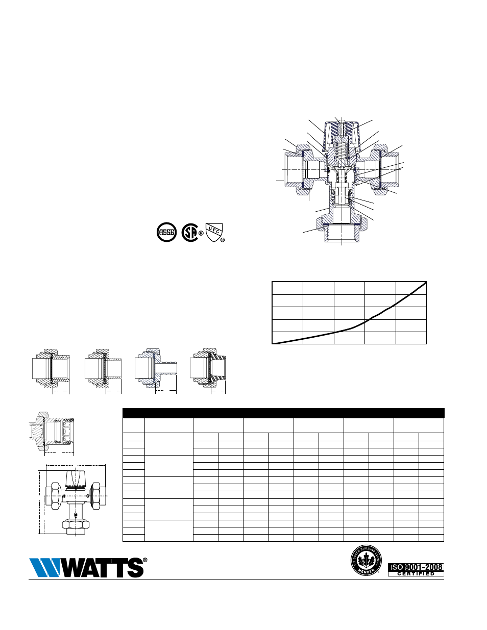
kpa psi
345 50
276 40
207 30
138 20
69 10
0
0 5 10 15 20 25
gpm
19 38 57 76 95
lpm
pressure Drop
Flow
Flow curves are for reference. Actual flows may vary
depending on system temperatures and/or pressures.
***Flow curve with integral inlet filters check valves
Capacity***
Dimensions — Weights
THREAD
(UT)
SWEAT
(US)
CPVC
PEX
D
D
D
D
D
QUICK-CONNECT
(QC)
'
D
'
a
B
C
Hot
Water
Inlet
Mixed Outlet
Cold
Water
Inlet
SIZE
MODEL
DIMENSIONS
WEIgHT
A
B
C
D
in.
in.
mm.
in.
mm.
in.
mm.
in.
mm.
lbs.
kg.
1
⁄
2
LF1170-UT-M2
4
7
⁄
8
124
5
7
⁄
16
137
3
3
⁄
16
80
5
⁄
8
16
1.8
0.8
3
⁄
4
4
7
⁄
8
124
5
7
⁄
16
137
3
3
⁄
16
80
5
⁄
8
16
2.4
1.1
1
5
5
⁄
16
135
5
5
⁄
8
143
3
3
⁄
8
86
3
⁄
4
20
3.0
1.4
1
⁄
2
LF1170-US-M2
4
13
⁄
16
123
5
3
⁄
8
137
3
1
⁄
8
80
5
⁄
8
15
1.7
0.8
3
⁄
4
5
5
⁄
16
135
5
5
⁄
8
143
3
3
⁄
8
86
7
⁄
8
22
2.3
1.0
1
5
13
⁄
16
148
5
7
⁄
8
149
3
5
⁄
8
92
1
1
⁄
8
28
2.9
1.3
1
⁄
2
LF1170-PEX-M2
5
1
⁄
4
133
5
9
⁄
16
142
3
5
⁄
16
85
13
⁄
16
21
1.8
0.8
3
⁄
4
5
1
⁄
2
140
5
11
⁄
16
145
3
7
⁄
16
88
15
⁄
16
24
2.5
1.1
1
5
7
⁄
8
149
5
7
⁄
8
150
3
5
⁄
8
93
1
1
⁄
8
29
3.1
1.4
1
⁄
2
LF1170-CPVC-M2
4
3
⁄
4
121
5
5
⁄
16
136
3
1
⁄
16
79
9
⁄
16
14
1.6
0.7
3
⁄
4
5
1
⁄
4
133
5
9
⁄
16
142
3
5
⁄
16
85
13
⁄
16
21
2.2
1.0
1
5
11
⁄
16
144
5
13
⁄
16
147
3
9
⁄
16
90
1
26
2.6
1.2
1
⁄
2
LF1170-QC-M2
6
5
⁄
8
168
6
1
⁄
4
159
4
102
1
1
⁄
2
38
2.1
0.9
3
⁄
4
6
15
⁄
16
177
6
7
⁄
16
163
4
3
⁄
16
106
1
11
⁄
16
42
2.8
1.3
1
7
1
⁄
8
181
6
1
⁄
2
165
4
1
⁄
4
108
1
3
⁄
4
44
3.5
1.6
Specifications
A Hot Water Temperature Control Valve shall be installed on water
heating equipment to provide tempered water to supply piping. Valve
shall have a Lead Free* copper silicon alloy body. Lead Free* ther-
mostatic valves shall comply with state codes and standards, where
applicable, requiring reduced lead content. The valve shall have inte-
gral check valves and operate so the thermostat controls the cold
and hot water ports. The valve shall be provided with solder (-US),
threaded (-UT), PEx (-PEx), Quick-Connect (-QC) or CPVC (-CPVC)
connections. Valve shall be ASSE Standard 1017** Listed. Valve shall
be a Watts Series LF1170-M2 or LFL1170-M2.
Pressure — Temperature
Minimum Supply Pressure (Static): 30psi (207 kPa)
Inlet Temperatures: hot inlet, 120°F – 200°F (49°C – 93°C),
cold inlet, 40°F – 85°F (4°C – 29°C)
Hot Water Inlet to Outlet Temperature Differential: 5°F (3°C)
above
set
point
LF1170-M2 Temperature Out: Field range: 90°F – 160°F (32°C – 71°C),
adjustable: Accurate within ±3°F (1.7°C)
LFL1170-M2 Temperature Out: Field range: 60°F – 120°F (16°C – 49°C),
adjustable. Accurate within ±3°F (1.7°C)
Maximum Temperature: 200°F (93°C)
Maximum Pressure: 150psi (10.3 bar)
Maximum Pressure Differential Between Hot and Cold Water
Supplies: 25%.
Approval: CSA B125 certified
Listing: ASSE 1017 and IAPMO UPC
Basic Construction
lOCKiNg
aDJUSTmeNT Cap
aDapTeR
O-RiNg
STem aSSemBlY
O-RiNg
O-RiNg
BONNeT aSSemBlY
plUNgeR
SeaT
SpRiNg
THeRmOSTaT
FUNNel
UNiON NUT
FilTeR
WaSHeR
TailpieCe
CHeCK mODUle
BODY
FiBeR WaSHeR
FilTeR WaSHeR
alleN HeaD SCReW
ES-LF1170_LFL1170 1324
© 2013 Watts
USA: Tel: (978) 688-1811 • Fax: (978) 794-1848 • www.watts.com
Canada: Tel: (905) 332-4090 • Fax: (905) 332-7068 • www.watts.ca
A Watts Water Technologies Company
Material
Body:
Lead Free* copper silicon alloy
Springs:
Stainless steel
Thermostat Assembly: Copper
O-Rings: EPDM
Pistons: Polysulfone