Watts N30 User Manual
Relief valves, Pressure relief only: types n30, n30l, Diaphragm actuated
IS-N30
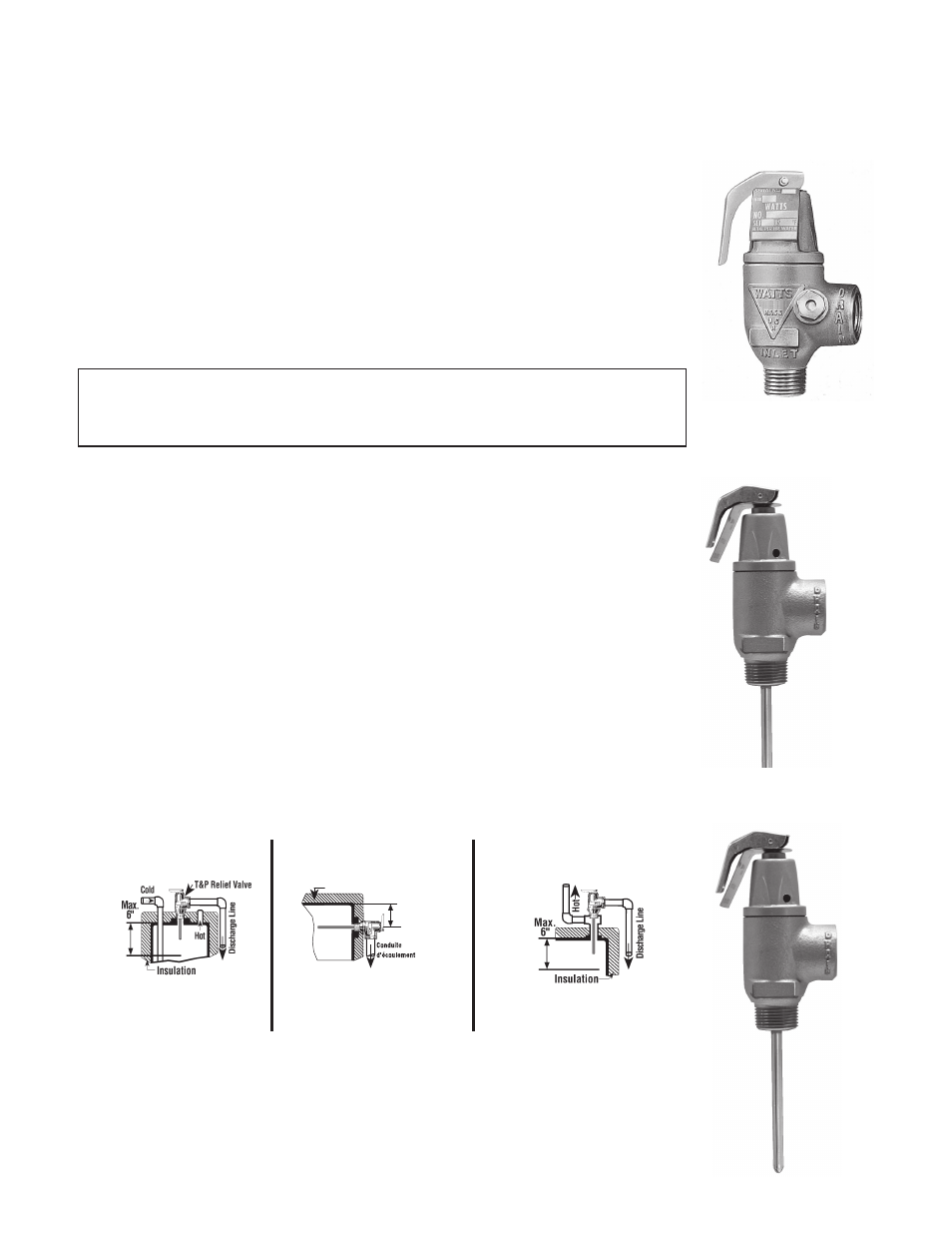
Correct Installation of T&P Relief Valves
Always use an extension type thermo-
stat T&P relief valve which permits the
end of the thermostat to extend into the
top 6” of the tank.
For internal fl ue heaters, a T&P relief valve
with a short or standard length thermostat
can be used. For external fl ue heaters,
see below.
For Heaters With Direct
Side Tapping
For Heaters With Direct
Top Tapping
“Alternate” Only when the
tappings are not provided
Max. 6”
(152mm)
Max. 6”
(152mm)
Max
152 mm
Isolation
Max. 6”
(152mm)
Combination temperature and pressure relief valves with extension thermostats must be installed
so that the temperature-sensing element is immersed in the water within the top 6" (152mm) of the
tank. They must be installed either in the hot outlet service line or directly in a tank tapping. Combi-
nation temperature and pressure relief valves that do not have extension elements must be mounted
directly in a tank tapping located within the top 6" (152mm) of the tank. They shall be adequately
insulated and located so as to assure isolation from fl ue gas heat or other ambient conditions that are
not indicative of stored water temperature. To avoid water damage or scalding due to valve opera-
tion, drain pipe must be as short as possible and be the same size as the valve discharge connec-
tion throughout its entire length. Drain line must pitch downward from the valve and terminate at
least 6” (152mm) above the fl oor drain where any discharge will be clearly visible. The drain line shall
terminate plain, not threaded, with a material serviceable for temperatures up to 250°F (121°C) or
greater. Excessive length, over 30’ (9.14m), or use of more than four elbows can cause a restriction
and reduce the discharge capacity of the valve. No shutoff valve shall be installed between the relief
valve and tank, or in the drain line. Valve lever must be tripped at least once a year to insure that
waterways are clear. This device is designed for emergency safety relief and shall not be used as an
operating control.
Temperature and Pressure Relief:
Types M31SL, M31XL
Installation
IMPORTANT
These valves protect against excessive pressure only. To prevent excessive temperature above
212°F, which might result in a hot water explosion, combined temperature and pressure protection is
essential. WATTS Combination Temperature and Pressure Relief Valves below give this protection.
Pressure is common to all parts of a system so valve may be installed in either hot or cold water line
but as near as possible to tank or heater. Run the drain pipe to open fl oor drain, never outside the
building. Never install a valve of any kind in the drain line or obstruct in any way. The maximum set
pressure is stamped on the valve body. Valves should be ordered to relieve not less than 25-30 lbs.
above the maximum service main pressure but never above the maximum allowable working pres-
sure of tank.
Pressure Relief Only: Types N30, N30L
Installation Instructions
IMPORTANT: A relief valve functions, in an emergency, by discharging water. Therefore, it is es-
sential that a discharge line be piped from the valve in order to carry the overfl ow to a safe place of
disposal. The drain pipe must be the same size as the valve outlet, and must pitch downward from
the valve.
No. N30 without lever
No. N30L with lever
No. M31SL
No. M31XL
Relief Valves
Diaphragm Actuated
IS-N30.indd 1
9/15/08 2:58:34 PM