Parts needed, Installation steps – Watts PWPERMKIT User Manual
Page 3
3
Permeate Pump Installation
with the Standard System
Parts Needed
(1) Permeate Pump with mounting clip
(1) 48" long,
1
⁄
4
" Blue tube
NOTE: When mounting the Permeate Pump, make sure the
outlet ports of the Permeate Pump are above the inlet ports in
order to allow entrapped air to escape
1. Turn off the incoming water to the reverse osmosis unit. Lift the
handle on the reverse osmosis drinking water faucet to drain the
water from the system and storage tank .
Note: If tank is equipped with a ball valve, close valve to
preserve the tank water.
2. Before installing the Permeate Pump, remove the blue tube in-
serts from the ports . Refer to the diagram on Page 2 for instruc-
tions for disconnecting from a Quick-Connect fitting .
3 . Cut the blue tube between the shutoff valve and the membrane
housing . Then insert the end from the reverse osmosis mem-
brane into the Permeate Pump “PERMEATE IN” port .
4 . Insert the tube from the shutoff valve into the Permeate Pump
“PERMEATE OUT” port . Use the additional blue tubing if extra
length is needed .
5 . Cut the
1
⁄
4
" waste line from the membrane (after the flow restric-
tor) and insert the tube from the membrane into the Permeate
Pump “BRINE IN” port (Make sure the flow restrictor is located
between the Permeate Pump and the membrane).
6 . Insert the
1
⁄
4
" red tube from the faucet air gap inlet into the
Permeate Pump “BRINE OUT” port.
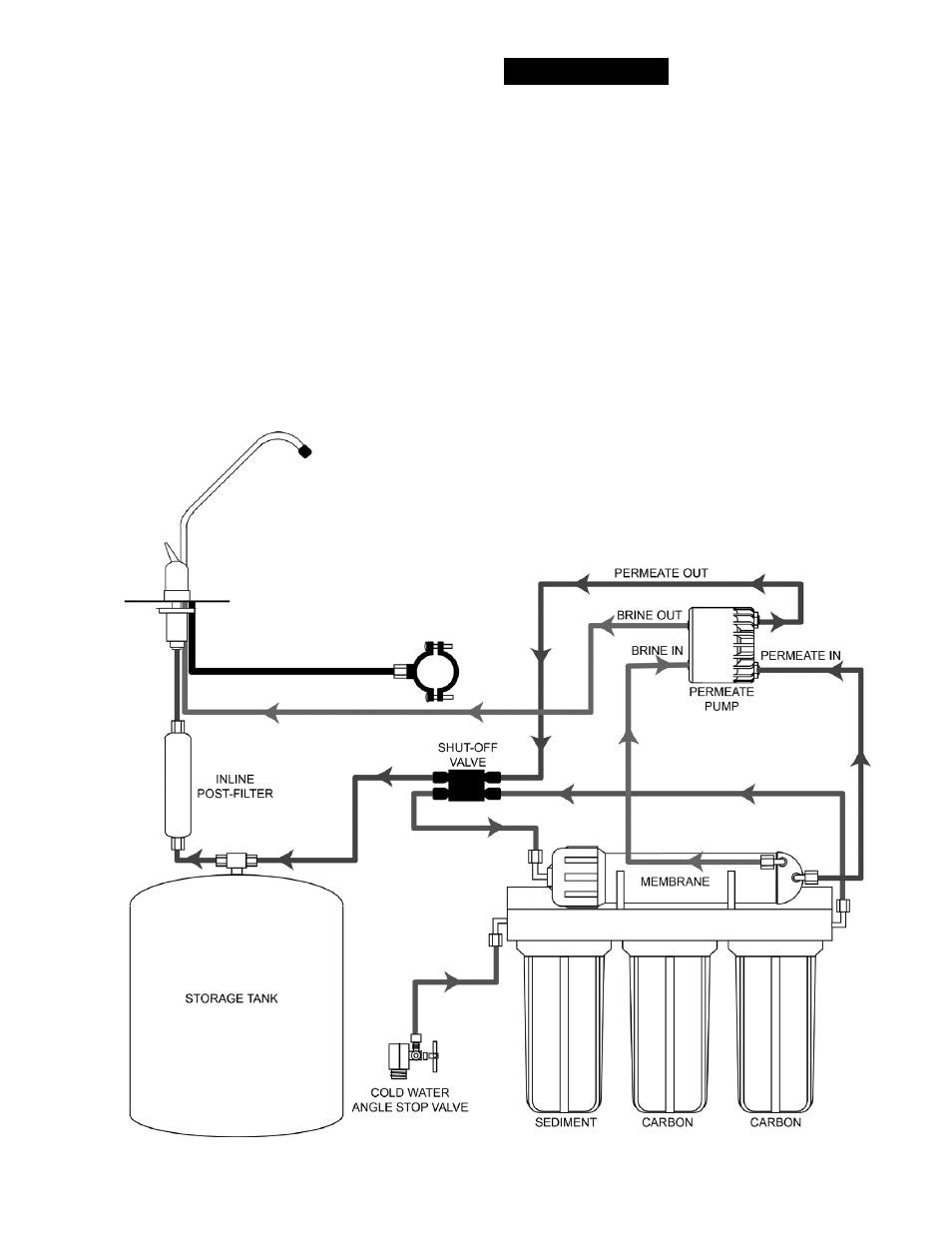
7 . Make sure your installation matches the diagram shown in
Figure 1.
8 . Turn on the water supply . Check for leaks periodically for the
next 24-48 hours as the system fills and again after it shuts off
when the tank is full .
Figure 1: Standard System after installation of Permeate Pump
Installation Steps
3
⁄
8
" BLACK TUBE DRAIN
RED TUBE
BLUE TUBE
BLUE TUBE
GREEN TUBE
GREEN TUBE
RED TUBE