Watts 315-M2 User Manual
Series 315, Steam safety valves, Size
For Low Pressure Steam Boilers and Process Equipment
ES-315-M2
Job Name –––––––––––––––––––––––––––––––––––––––––––
Contractor ––––––––––––––––––––––––––––––––––––––––––––
Job Location –––––––––––––––––––––––––––––––––––––––––
Approval –––––––––––––––––––––––––––––––––––––––––––––
Engineer –––––––––––––––––––––––––––––––––––––––––––––
Contractor’s P.O. No. –––––––––––––––––––––––––––––––––––
Approval –––––––––––––––––––––––––––––––––––––––––––––
Representative ––––––––––––––––––––––––––––––––––––––––
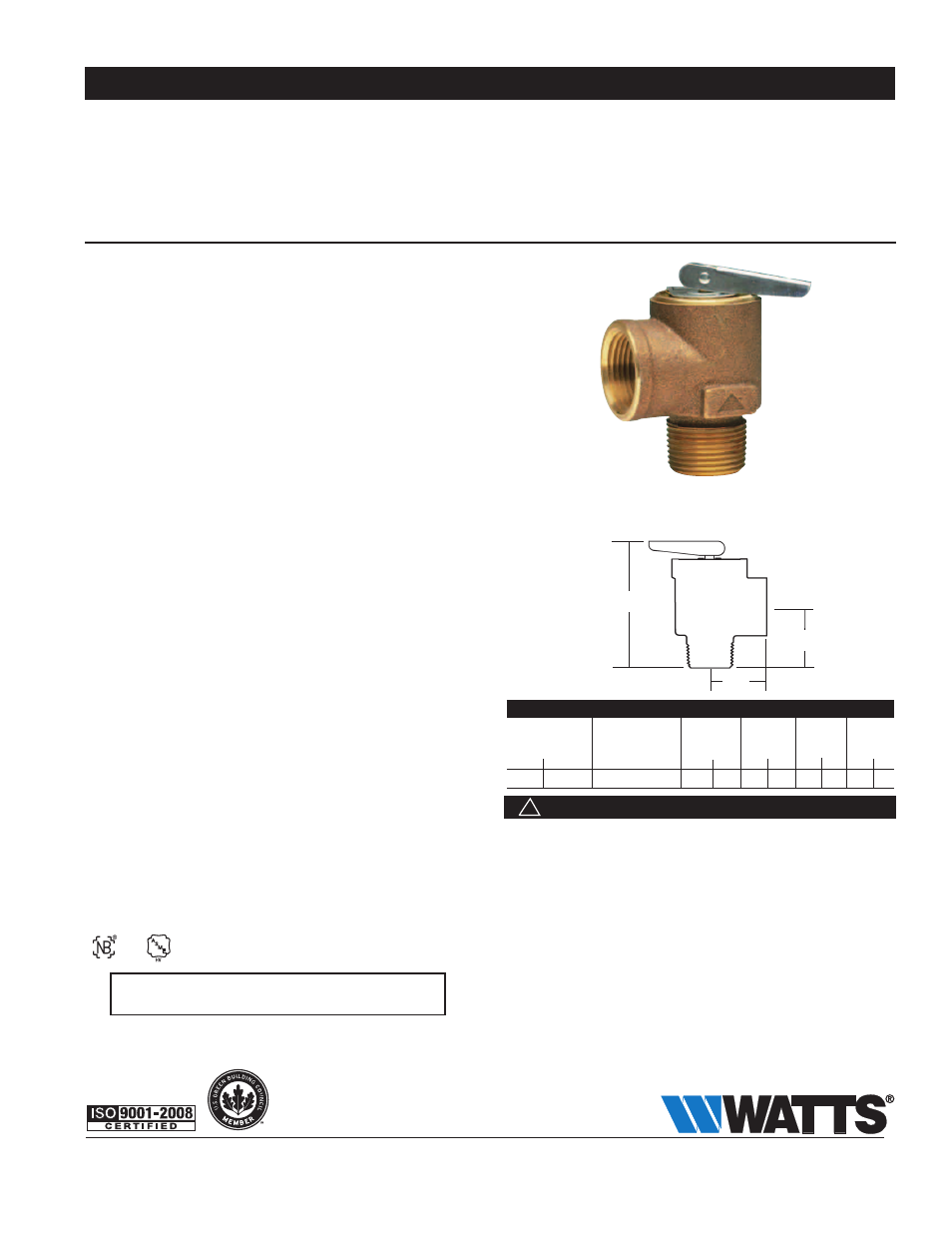
Series 315
Steam Safety Valves
Size:
3
⁄
4
" (20mm)
Series 315 ASME rated Steam Safety Relief Valves provide high
quality dependable low cost protection for any low pressure steam
heating equipment operating up to 15psi. Available at lower set-
tings, such as 8psi for pressure cooker and steam cleaning
equipment requirements. Consult your local Watts agent for ratings
at lower pressure settings.
Series 315 features a bronze body and stainless steel spring. A top
guided stem and non-stick PTFE
®
disc to metal seating ensures
positive shutoff. Capacity at 15psi is 375 lbs./hr.
Features
• High capacity
• Positive shut off
• Non-sticking PTFE
®
disc
• Seat located above drain
• NPT threaded male inlet x threaded female outlet
(drain) connection
Models
L – Extended inlet shank to accommodate thick insulation
SC – Satin chrome finish
Specifications
Steam Safety Relief Valve shall be installed on the boiler where
noted on the plans. Valve shall be manufactured out of bronze with
stainless steel spring, non-stick PTFE
®
disc, and metal seat. Valve
shall have a maximum operating pressure of 15psi. Valve shall be a
Watts Regulator Company Series 315.
Materials
Body: Bronze
Spring: Stainless Steel
Disc: Non-stick PTFE
®
Seating: Bronze
Pressure — Temperature
Capacity at 15psi is 375 lbs./hr.
Approvals
Dimensions — Weights
siZe (dn)
dimensions
Weight
ASME STEAM
Discharge Capacity
A
B
C
in. mm lbs./hr. @
15psi in. mm in. mm in. mm lbs. kg.
3
⁄
4
x
3
⁄
4
20 x 20
375
2
3
⁄
4
70 1
3
⁄
8
35 1
1
⁄
4
32 .46 .21
ES-315-M2 1210
© 2012 Watts
USA: Tel. (978) 688-1811 • Fax: (978) 794-1848 • www.watts.com
Canada: Tel. (905) 332-4090 • Fax: (905) 332-7068 • www.wattscanada.ca
Watts product specifications in U.S. customary units and metric are approximate and are provided for reference only. For precise measurements, please contact Watts Technical Service. Watts
reserves the right to change or modify product design, construction, specifications, or materials without prior notice and without incurring any obligation to make such changes and modifications
on Watts products previously or subsequently sold.
A Watts Water Technologies Company
315-M2
B
A
C
Following installation, the valve lever MUST be operated AT
LEAST ONCE A YEAR to ensure that the water-ways are clear.
Certain naturally occurring mineral deposits may adhere to the valve,
rendering it inoperative. When manually operating the lever, water
will discharge and precautions must be taken to avoid contact with
hot water and to avoid water damage. BEFORE
operating lever,
check to see that a discharge line is connected to this valve directing
the flow of hot water from the valve to a proper place of disposal
otherwise personal injury may result. If no water flows, valve is inop-
erative.
CALL A PLUMBER IMMEDIATELY.
This device is designed for emergency safety relief and shall not be
used as an operating control.
WARNING
!
IMPORTANT: INQUIRE WITH GOVERNING AUTHORITIES
FOR LOCAL INSTALLATION REQUIREMENTS