Sample installation #1 wiring diagram #1, 8 - 40mm) wiring diagram #2, 8 - 40mm) – Watts EMVII-6400-SS User Manual
Page 3: Sample installation #2, Terminal function
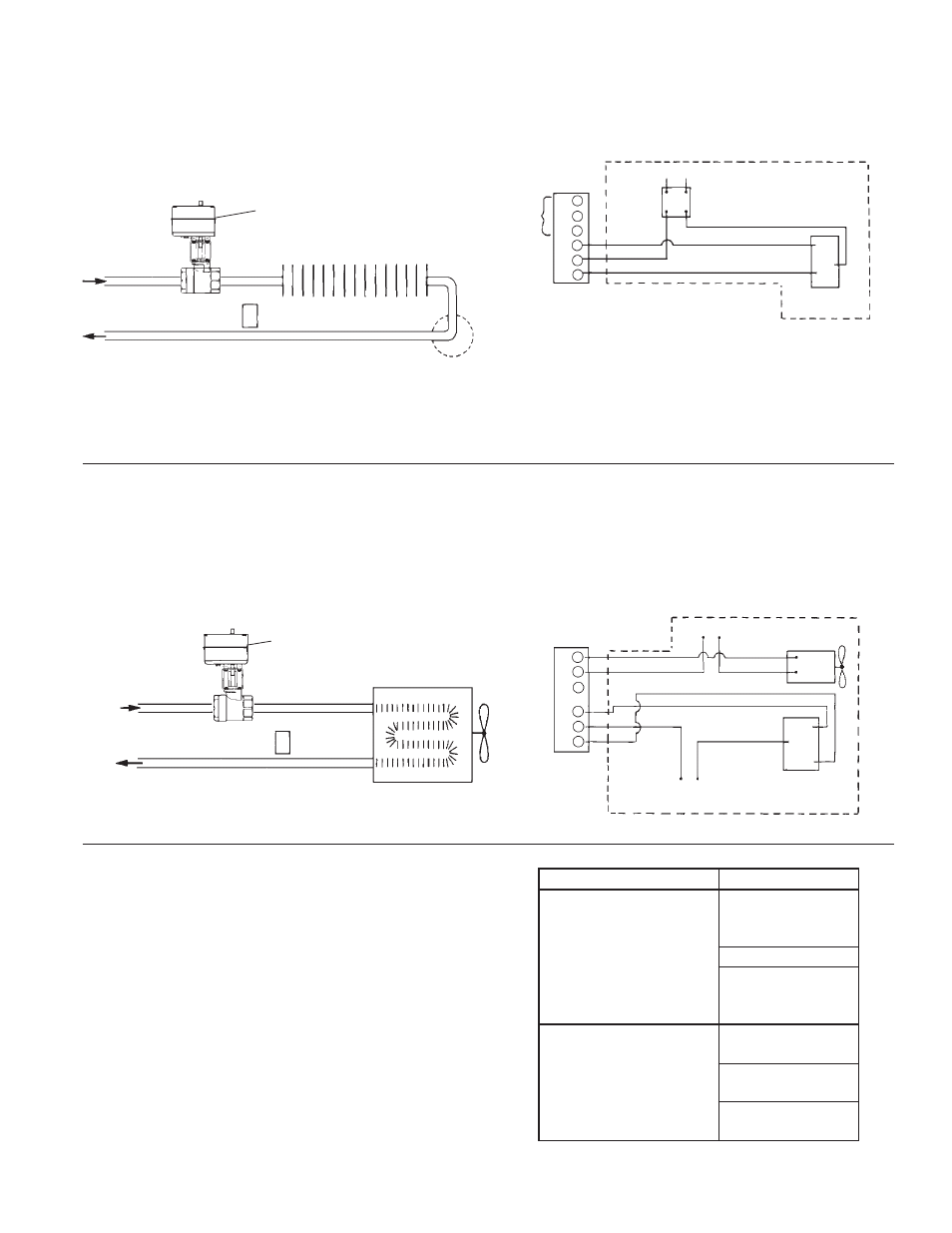
Sample Installation #1
Wiring Diagram #1
1
⁄
4
" - 1
1
⁄
2
" (8 - 40mm)
Wiring Diagram #2
1
⁄
4
" - 1
1
⁄
2
" (8 - 40mm)
Use of Watts Electric Motor Valve as a zone control for
hot water or steam space heating. Valve opens upon
temperature drop. Closes when demand for heat is
satisfi ed.
Electrical diagram with 24V control circuit, 24V Motor
Valve, SPDT thermostat.
Heat Transfer Means
Hot Water or
Steam In
Hot Water Return, or
Steam Condensate
Return
Steam Trap
(Steam System)
Watts Motor Valve
Thermostat (SPDT)
Auxiliary
Switch
Terminals
Motor Valve
Terminals
(24V)
24V Transformer
See Note
115V Line
24V SPDT
Thermostat
Customer Supplied
External Components
Note:
1
⁄
4
"-1
1
⁄
2
" (8 - 40mm) EMVII-6400SS-24-45 will operate with a 40
VAC transformer. Thermostat must be capable of handling amp rating
at stall (see page 2- Operating Data) or relay must be added to circuit.
1
2
3
4
5
6
A = Common
B = Normally Open
C = Normally Closed
Sample Installation #2
Cooling with refrigerated water and operating forced air
fan with auxiliary switch. Motor Valve opens and starts
blower upon temperature rise. Shuts off blower and
closes when temperature drops to thermostat setting.
Electrical diagram with 115V control circuit, 115V Mo-
tor Valve, line voltage SPDT cooling thermostat, 115V
blower.
Watts Motor Valve
Thermostat
Cooling Coil
Cold Water Return
Cold Water In
Forced
Air
Fan
A = Common
B = Normally Open
C = Normally Closed
Motor Valve
Terminals
(115V)
115V Fan
Motor
115V Line
115V SPDT Cooling
Thermostat
115V Line
1
2
3
4
5
6
B
A
C
Terminal Function
1
⁄
4
" - 1
1
⁄
2
" (8 - 40mm)
1
⁄
4
"-1
1
⁄
2
" (8 - 40mm) motor valves are supplied with wiring termi-
nal strips having six terminals. Terminals 4, 5 and 6 operate the
motor valve, while terminals 1, 2 and 3 are connected to
an internal SPDT auxiliary switch.
Note: 24 VAC or 115 VAC models, the following terminal
explanation will always apply.
B
A
C
Customer Supplied
Exter
nal Components
Terminal No.
Function
Operating Terminal #4
When power
is applied,
valve will open
Operating Terminal #5
Common
Operating Terminal #6
When power
is applied
valve will Close
Auxiliary Switch
Terminal #1
Makes when
valve opens
Auxiliary Switch
Terminal #2
Common
Auxiliary Switch
Terminal #2
Makes when
valve closes