Watts Dead Level P User Manual
Page 2
Concrete Pour
Check the entire trench system for proper anchoring, alignment, and
leveling, prior to pouring concrete. Although the Dead Level frame-
anchored design dramatically reduces the risk of floating, a poorly
anchored system can shift during the pour. Check the excavation to
be sure a minimum of 4" of concrete can be poured under, and on
all sides of the channels. The concrete must be adequately vibrated
as it is placed, to ensure complete filling of all potential voids around
the trench. The top edge of the trench frame should be approx. 1/16"
below grade after finish troweling to keep the frame at or below grade
after the concrete is fully cured.
Final Inspection
After the concrete is dry, remove the construction covers, and re-
tighten the grate lockdowns. If construction covers will not pry out
easily, cut the cover, and loosen the grate lockdown to free the sides
of the cover.
Retro-Fit or Suspended Installations
Cut the existing slab or form a cavity which will enable a 4" concrete
pour below and around the Dead Level system. Cut 2x4’s at least
30" in length to span the cavity, and align 2x4’s with the cross bars
in the trench frame. Drill 1/2" holes to secure the 2x4’s to the frame
cross bars, using 3/8-16x4-1/2" (minimum) bolts and washers (Fig. K
). Insert a thin shim between 2x4’s and the frame to ensure the trench
will sit slightly below finished grade after the pour. Securely anchor the
2x4’s to grade to prevent floating. Once the concrete is initially set,
remove 2x4’s and complete unfinished areas with concrete. Install the
grates & lockdowns.
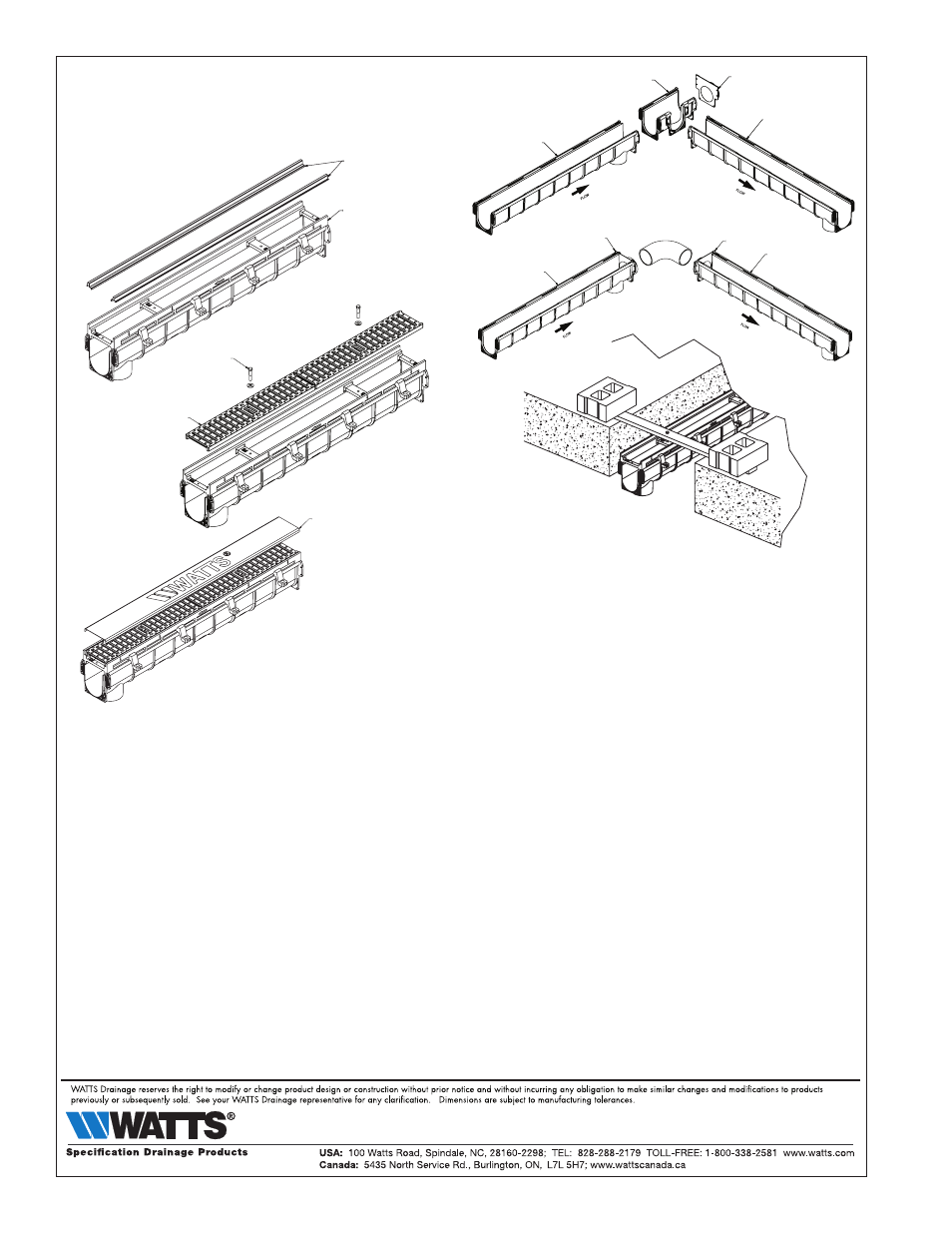
Grate Installation
Grates should always be installed prior to the concrete pour.
If used, install Frames Guards prior to setting the grates (Fig. F). Install
grates along the length of the trench, and secure with hex head or
countersunk lock bolts provided (Fig. G). Position Construction Covers
over the grates, with the flange between the grate and frame (Fig. H).
Corners/Tees
If the system layout requires Corner/Tee Sections, follow the general
installation guidelines. Invert the Corner/Tee section on a flat surface,
and use a reciprocating saw to remove the appropriate cutout(s) on
the section. Be sure to note whether the connecting channel(s) have
a tongue or groove connection prior to cutting the Corner/Tee, and
remove a cutout opposite the connecting channel. With the cutout
correctly removed, the tongue should slide inside the mating groove,
and the flanges should sit flush against each other (Fig. I). Secure the
channels and frames with the appropriate hardware (see “Joint Con-
nections").
Note Dead Level corners or tees can also be formed with a Catch Ba-
sin (See “Catch Basins & Piping Connections"), or underground pip-
ing. To pipe underground, terminate the trench drains a short distance
from the corner joint. Attach the appropriate endcaps, then connect
the endcaps with 4" Sch40 90’s, tees, and piping as required (Fig. J).
FIG. F
FRAME GUARDS
(OPTIONAL)
CHANNEL & FRAME
FIG. G
LOCK DOWN
GRATES
FIG. H
CONSTRUCTION COVER
FIG. I
END CAP
STANDARD
SECTION
STANDARD
SECTION
CORNER / TEE SECTION
STANDARD SECTION
FIG. J
END CAP
END CAP
STANDARD
SECTION
STANDARD
SECTION
FIG. K
LIMITED WARRANTY:
Watts Regulator Co. (the “Company”) warrants each product to be free from defects in material and workmanship under normal usage for a period of one year from the date of original shipment. In the event of such defects within
the warranty period, the Company will, at its option, replace or recondition the product without charge.
THE WARRANTY SET FORTH HEREIN IS GIVEN EXPRESSLY AND IS THE ONLY WARRANTY GIVEN BY THE COMPANY WITH RESPECT TO THE PRODUCT. THE COMPANY MAKES NO OTHER WARRANTIES, EXPRESS OR IMPLIED. THE
COMPANY HEREBY SPECIFICALLY DISCLAIMS ALL OTHER WARRANTIES, EXPRESS OR IMPLIED, INCLUDING BUT NOT LIMITED TO THE IMPLIED WARRANTIES OF MERCHANTABILITY AND FITNESS FOR A PARTICULAR PURPOSE.
The remedy described in the first paragraph of this warranty shall constitute the sole and exclusive remedy for breach of warranty, and the Company shall not be responsible for any incidental, special or consequential damages,
including without limitation, lost profits or the cost of repairing or replacing other property which is damaged if this product does not work properly, other costs resulting from labor charges, delays, vandalism, negligence, fouling
caused by foreign material, damage from adverse water conditions, chemical, or any other circumstances over which the Company has no control. This warranty shall be invalidated by any abuse, misuse, misapplication, improper
installation or improper maintenance or alteration of the product.
Some States do not allow limitations on how long an implied warranty lasts, and some States do not allow the exclusion or limitation of incidental or consequential damages. Therefore the above limitations may not apply to you.
This Limited Warranty gives you specific legal rights, and you may have other rights that vary from State to State. You should consult applicable state laws to determine your rights. SO FAR AS IS CONSISTENT WITH APPLICABLE
STATE LAW, ANY IMPLIED WARRANTIES THAT MAY NOT BE DISCLAIMED, INCLUDING THE IMPLIED WARRANTIES OF MERCHANTABILITY AND FITNESS FOR A PARTICULAR PURPOSE, ARE LIMITED IN DURATION TO ONE YEAR FROM
THE DATE OF ORIGINAL SHIPMENT.
IS-WD-DL-Installation 1104
EDP# 2915867
DL-Instatllation