Identification of control valving, Flow diagrams, Valve disc principle of operation – Watts N2050A User Manual
Page 13: 2 backwash position, 1 service position
13
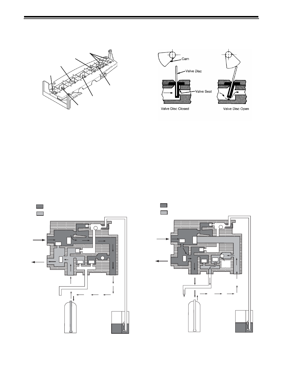
Identification of Control Valving
2 Backwash Position
1 Brine Valve
2 Bypass Valve
3 Inlet Valve
4 Outlet Valve
5 Refill Valve
6 Rinse Drain Valve
7 Backwash Drain Valves
Flow Diagrams
Mineral Tank
Brine
Adjustment
Brine Tank
Mineral Tank
Drain
Inlet
Outlet
Hard Water
Soft Water
5
4
1
3
2
6
7
Mineral Tank
Brine
Adjustment
Brine Tank
Mineral Tank
Drain
Inlet
Outlet
Hard Water
Soft Water
5
4
1
3
2
6
7
Backwash
Flow
Control
Valve
No.
1 - Closed
2 - Closed
3 - Open
4 - Open
5 - Closed
6 - Closed
7 - Closed
Valve
No.
1 - Closed
2 - Open
3 - Closed
4 - Open
5 - Closed
6 - Closed
7 - Open
1 Service Position
Valve Disc Principle of Operation