Watts 994 User Manual
Series 994, Lead free, Re duced pres sure zone assemblies
994OSY
Models
Suffix:
NRS –
non-rising stem resilient seated gate valves
OSY –
UL/FM outside stem & yoke resilient seated gate valves
**OSY FxG – flanged inlet gate connection and grooved outlet gate connection
**OSY GxF – grooved inlet gate connection and flanged outlet gate connection
**OSY GxG – grooved inlet gate connection and grooved outlet gate connection
LF –
without shutoff valves
S –
cast iron strainer
Available with grooved NRS gate valves - consult factory**
Post indicator plate and operating nut available - consult factory**
**Consult factory for dimensions
Note: The installation of a drain line is recommended. When in stall ing a drain line,
a 994AGK-P air gap is necessary. See ES-AG/EL/TC for additional information.
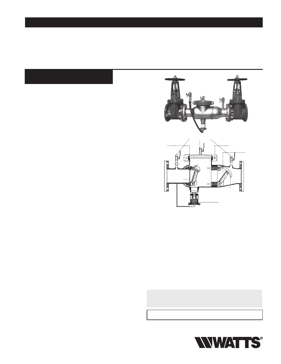
Series 994
Re duced Pres sure Zone Assemblies
Sizes: 2
1
⁄
2
" – 10" (65 – 250mm)
Series 994 Re duced Pressure Zone Assemblies are de signed to pro
vide pro tec tion of the potable water supply in ac cor dance with na tion al
codes. This series can be used where ap proved by the local au thor i ty hav ing
ju ris dic tion on health hazard crosscon nec tions. Se ries 994 fea tures a short lay
length, light weight stain less steel body, cor ro sion re sis tant stainless steel
re lief valve, and patented tor sion spring check valves.
Features
• Stainless steel construction provides long term corrosion resistance
and maximum strength
• Stainless steel body is half the weight of com pet i tive designs reducing
installation & shipping costs
• Short end-to-end dimensions makes retrofit easy
• Bottom mounted relief valve reduces clearance re quire ments when
installed against an outside wall
• Torsion spring check valves provides maximum flow at low
pressure drop
• Thermoplastic & stainless steel check valves for trouble-free operation
• No special tools required for servicing
• Compact construction allows for smaller enclosures
• Stainless steel relief valve features a balanced rolling diaphragm to eliminate
sliding seals and lower maintenance costs
Specifications
A Reduced Pressure Zone Assembly shall be installed at each crosscon
nec tion to prevent backsiphonage and backpressure of haz ard ous ma te ri
als into the potable water supply. The assembly shall consist of a pres sure
differential relief valve located in a zone be tween two pos i tive seating
check valves. The main valve body shall be man u fac tured from 300 Series
stainless steel for corrosion re sis tance. The check valves shall be of
thermoplastic construction with stain less steel hinge pins, cam arm, and
cam bearing. The check valve shall uti lize a single tor sion spring design
to minimize pressure drop through the as sem bly. The check valves shall
be modular and shall seal to the main valve body by the use of an Oring.
There shall be no brass or bronze parts used with in the check assembly
or relief valve. The use of seat screws to re tain the check valve seat is
prohibited. All internal parts shall be ac ces si ble through a single cover on
the valve assembly se cure ly held in place by a twobolt grooved coupling.
The dif fer en tial relief valve shall be of stain less steel con struc tion and shall
utilize a rolling di a phragm and no sliding seals. The relief valve shall be
bot tom mount ed and supplied with a steel reinforced sensing hose. The
assembly shall include two resilient seated shutoff valves & four ball type
test cocks. The assembly shall be a Watts Series 994.
Now Available
WattsBox Insulated Enclosures.
For more information, send for literature ES-WB.
IMPORTANT: INQUIRE WITH GOVERNING AUTHORITIES
FOR LOCAL INSTALLATION REQUIREMENTS
Test Cocks
Stainless Steel
Cover
Grooved Coupling
Disc
Replaceable
Seat
Torsion
Spring
Laser Cut/Polished
Cam Arm
Stainless Steel
Relief Valve
For Health Hazard Applications
ES-994
Job Name –––––––––––––––––––––––––––––––––––––––––––
Contractor –––––––––––––––––––––––––––––––––––––––––––
Job Location –––––––––––––––––––––––––––––––––––––––––
Approval ––––––––––––––––––––––––––––––––––––––––––––
Engineer –––––––––––––––––––––––––––––––––––––––––––––
Contractor’s P.O. No. –––––––––––––––––––––––––––––––––
Approval –––––––––––––––––––––––––––––––––––––––––––––
Representative –––––––––––––––––––––––––––––––––––––––
Watts product specifications in U.S. customary units and metric are approximate and are provided for reference only. For precise measurements,
please contact Watts Technical Service. Watts reserves the right to change or modify product design, construction, specifications, or materials with
out prior notice and without incurring any obligation to make such changes and modifications on Watts products previously or subsequently sold.
* The wetted surface of this product contacted by consumable water
contains less than one quarter of one percent (0.25%) of lead by weight.
LEAD FREE
*