Models, Materials, Connections – Watts LF909 User Manual
Page 2: Standards, Approvals, Pressure — temperature, Dimensions — weights, How it operates, Notice
Models
Suffix
QT
Quarter-turn ball valves
S
Bronze strainer
HW
Stainless steel check modules for hot and harsh
water conditions
The installation of a drain line is recommended.
When in stall ing a drain line, an air gap is necessary.
Materials
Body: Lead Free* Cast Copper Silicon Alloy
Check Seats: 909 Celcon
®
Relief Valve Seats: Stainless Steel 909HW
Test Cocks: Lead Free* Cast Copper Silicon Alloy
Celcon
®
is a registered trademark of Celanese, Limited
Connections
3
⁄
4
" – 1" (19 – 25mm) 909-NPT Female threaded body connec-
tion
1
1
⁄
4
" – 2" (32 – 50mm) 909-M1-NPT Male threaded
body con nec tion
Standards
AWWA C-511-92
FCCCHR of USC Manual Section 10
IAPMO (UPC), SBCCI (Standard Plumbing code)
Approvals
Listed by IAPMO
Listed by SBCCI
‡Approved by the Foundation for Cross-Connection Control and
Hydraulic Research at the University of Southern Cal i for nia.
Horizontal and vertical “flow-up" approval on
3
⁄
4
" (20mm) and
1" (25mm) sizes (model LF909QT).
Pressure — Temperature
Temperature Range: 33°F – 140°F (0.5°C – 60°C) continuos,
180°F (82°C) intermittent
Maximum Working Pressure: 175psi (12.1 bar)
Series LF909HW:
Temperature Range: 33°F – 210°F (0.5°C – 99°C)
Maximum Working Pressure: 175psi (12.1 bar)
L
A
S
B
E
S
C
D
Model LF909QT-S
P
Model LF909QT
E
L
A
Dimensions — Weights
When installing a drain line use 909AG series Air Gaps on
Series 909 back flow preventers. ††909EL se ries elbows are
for air gaps on back flow pre ven ters in vertical in stal la tions.
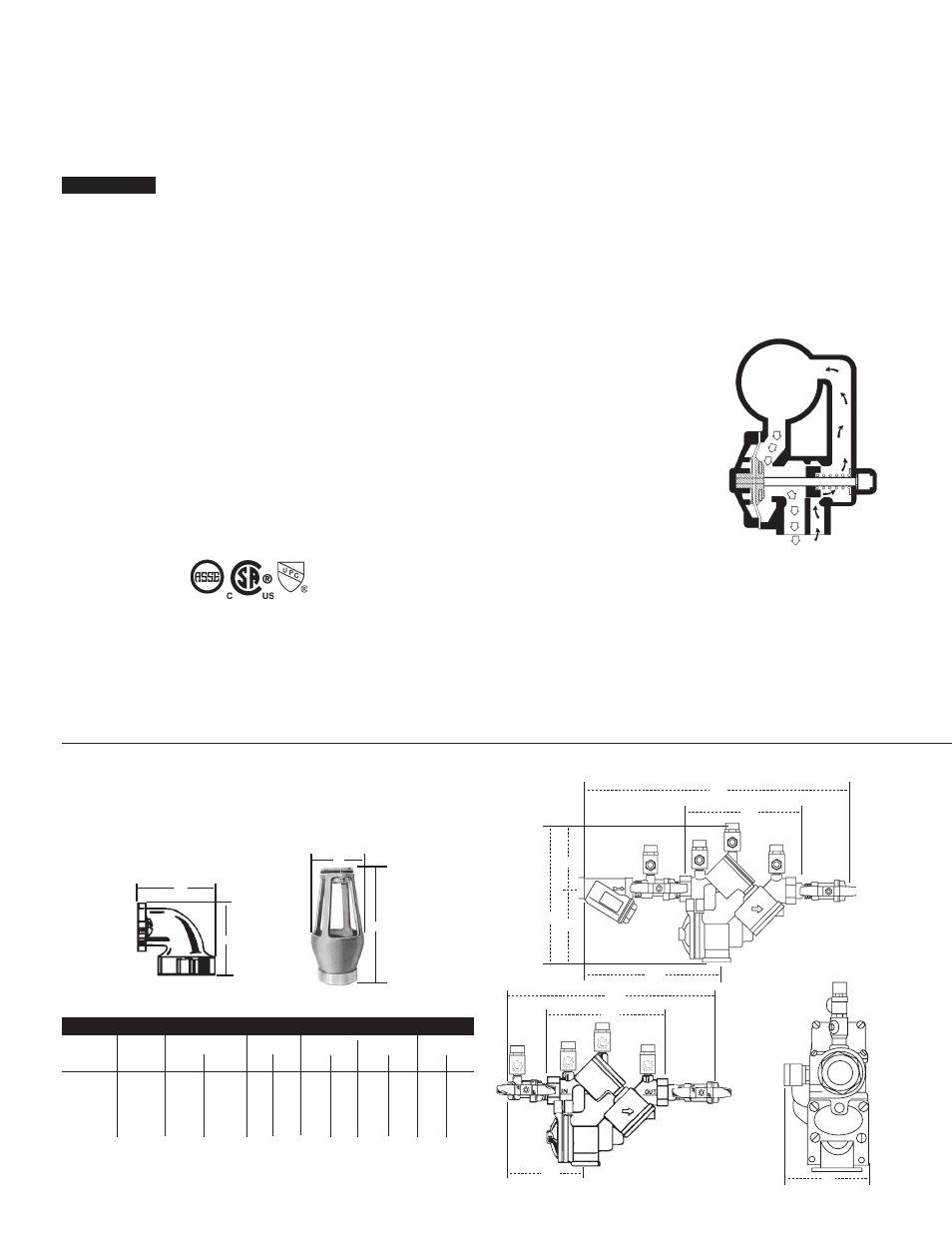
How it Operates
The unique relief valve con struc tion
in cor po rates two channels: one for
air, one for water. When the relief
valve opens, as in the ac com pa-
ny ing air-in/water-out di a gram, the
right-hand chan nel admits air to the
top of the re duced pressure zone,
re liev ing the zone vacuum. The chan-
nel on the left then drains the zone to
at mo sphere. Therefore, if both check
valves foul, and si mul ta neous nega-
tive supply and pos i tive backpressure
develop, the re lief valve uses the air-
in/water-out prin ci ple to stop potential
back flow.
Reduced
Pressure
Zone
WATER OUT
AIR IN
Series 909AG Air Gaps
909 DRAIN
OUTLET
DIMENSIONS
WEIghTS
Iron Body
Sizes
Sizes
A
B
No.
Desc.
in.
mm
in.
mm
in.
mm
in.
mm
lbs.
kg.
909AG-C Air Gap
3
⁄
4
,1 19,25 1 25 3
1
⁄
4
83 4
7
⁄
8
124 1
1
⁄
2
.7
909EL-C
Elbow††
3
⁄
4
,1 19,25 – – 2
3
⁄
8
60 2
3
⁄
8
60
3
⁄
8
.2
909AG-F
Air Gap 1
1
⁄
4
-2 32-50 2 50 4
3
⁄
8
111 6
3
⁄
4
171 3
1
⁄
4
1.5
909EL-F
Elbow†† 1
1
⁄
4
-2 32-50 – – 3
5
⁄
8
92 3
5
⁄
8
92 2 .9
A
B
A
B
1013 B64.4
NOTICE