Watts F1115-74 User Manual
Pressure reducing control valve, Low flow by-pass feature, Lassic
X – Isolation Cocks
○
FC – Flo-Clean Strainer
○
Y – Y-Strainer (Replaces Flo-Clean)
○
ACS – Adjustable Closing Speed
○
(Replaces Fixed Orifice)
AOS – Adjustable Opening Speed
○
P – Position Indicator
○
L – Limit Switch
○
8550 Hansen Road
•
Houston, Texas 77075
•
(Ph) 713.943.0688
•
(Fx) 713.944.9445
•
www.watts.com
06/08
C
lassiC
s
eries
Standard Components
Options & Accessories
(3)
(3)
(3)
(2)
(2)
(1)
(1)
Standard 3” & Smaller
Standard 4” & Larger
Optional All Sizes
(3)
(2)
(1)
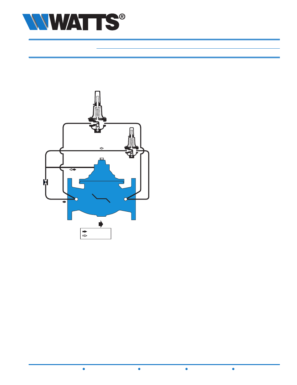
Schematics
Throttles to reduce high upstream pressure to
•
constant lower downstream pressure
Low Flow By-Pass controls at low flows
•
Main Line valve controls at high flows
•
Reducing and Low Flow By-Pass setpoints are
•
separately adjustable
(AOS)
P/L
2
3
4
CLOSES VALVE
OPENS VALVE
FLOW
X
X
X
1
Y/FC
F115-74 (Globe)
F1115-74 (Angle)
PRESSURE REDUCING CONTROL VALVE
with
LOW FLOW BY-PASS FEATURE
Operations
The Watts ACV Pressure Reducing Control Valve with Low Flow By-Pass is designed to automatically reduce
a fluctuating higher upstream pressure to a constant lower downstream pressure regardless of varying flow
rates. It is controlled by a normally open, pressure reducing pilot designed to: 1) Open (allowing fluid out of
the main valve cover chamber) when downstream pressure is below the adjustable setpoint, and 2) Close
(allowing fluid to fill the main valve cover chamber) when downstream pressure is above the adjustable
setpoint. A decrease in downstream pressure causes the valve to modulate toward an open position, raising
downstream pressure. An increase in downstream pressure causes the valve to modulate toward a closed
position, lowering downstream pressure.
A Low Flow By-Pass Valve is piped parallel to the Main Pressure Reducing Valve, and is set approximately
10 PSI higher. The Low Flow By-Pass handles flow requirements below the range of the Main Pressure
Reducing Valve. During “off peak” demand conditions, the Low Flow By-Pass provides flow and pressure
to the downstream zone. As flow requirements increase beyond the capacity of the Low Flow By-Pass,
downstream pressure falls below the setpoint of the Main Pressure Reducing Valve allowing it to throttle
toward open, supplementing flow and pressure. As flow requirements decrease, downstream pressure rises
above the setpoint of the Main Pressure Reducing Valve, causing it to throttle toward closed, allowing the Low
Flow By-Pass to resume command of flow and pressure.
1 – Main Valve (Single Chamber)
2 – Pressure Reducing Control
3 – Fixed Orifice
4 – Low Flow By-Pass