Test procedure for reduced pressure assembly, Test no. 4 - pressure differential relief valve, Test no. 1 - check valve no. 2 – Watts TK-99E User Manual
Page 3: Test no. 2 - shutoff valve no. 2, Test no. 3 - to test no. 1 check valve
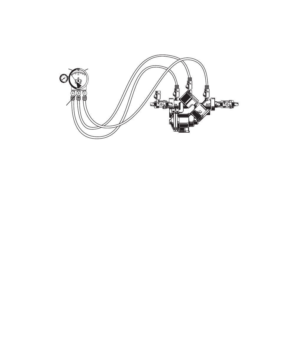
3
Test Procedure for Reduced Pressure Assembly
A. All needle valves must be closed on test kit.
B. Open test cock No. 4 and flush test cocks Nos. 1, 2 and 3 on reduced pressure assembly then close test cock No. 4.
C. Attach hoses as shown. Bleed air from kit, close No. 2 shutoff.
Test No. 4 - Pressure Differential Relief Valve
Purpose: To test operation of pressure differential relief valve.
Requirements: The pressure differential relief valve must
operate to maintain the “zone” between the two check valves
at least 2 PSI less than the supply pressure.
Step 1: Close needle valve “C” bypass (yellow).
Step 2: Open needle valve “A” high side (red).
Step 3: Open needle valve “B” low (blue) very slowly until the
differential gauge needle starts to drop.
Step 4: Hold the valve at this position and observe the gauge
reading at the moment the first discharge is noted
from the relief valve. Record this as the opening differ-
ential pressure of the relief valve. Note: it is important
that the differential gauge needle drops slowly.
Step 5: Close test cocks Nos. 2 and 3. Remove hose from
test cocks Nos. 2 and 3.
Step 6: Use bypass hose (yellow) to relieve pressure from
test kit by opening needle valve “A”, “B” and “C” and
bleed valves “A” and “B”.
Step 7: Remove all test equipment and open No. 2 shutoff
valve of the device.
Test No. 1 - Check Valve No. 2
Purpose: To test check valve No. 2 for tightness against
reverse flow.
Requirements: Valve must be tight against reverse flow under
all pressure differentials.
Step 1: Slowly open the needle valve “A” high side (red) and
“C” bypass (yellow). Keep the “B” low (blue) closed.
Step 2: Open test cock No. 4. Open test cock No. 2 and test
cock No. 3 after opening test cock No. 4.
Step 3: Indicated pressure differential will decrease slightly.
If pressure differential continues to decrease (until
the vent opens) the No. 2 check valve is reported as
“leaking”.
Test No. 2 - Shutoff Valve No. 2
Purpose: To test shutoff valve No. 2 for tightness.
Step 1: After passing Test No. 1, continue to test No. 2 by
closing test cock No. 2.
Step 2: The indicated pressure differential will decrease
slightly. If pressure differential continues to decrease
(approaching “zero”) the No. 2 shutoff valve is re-
ported to be “leaking”.
Note: A leaking No. 2 shutoff
will give a false reading in tests No. 3 and 4.
Test No. 3 - To test No. 1 Check Valve
Purpose: To test check valve No. 1 for tightness.
Requirements: Valve must be tight against reverse flow under
all pressure differentials.
Step 1: Close needle valve “A” high side (red) and open test
cock No. 2.
Step 2: Close test cock No. 4. Disconnect bypass hose (yel-
low) at test cock No. 4.
Step 3: Open needle valve “B” low (blue) and “C” bypass
(yellow), bleeding to atmosphere, then closing needle
valve “B” (blue) restores the system to a normal static
condition.
Step 4: Observe the pressure differential gauge. If there is a
decrease in the indicated value, the No. 1 check valve
is reported as “leaking”.
Bleed Valve A
Bleed Valve B
High
(red)
Low
(Blue)
Bypass
(yellow)
No. 2
Shutoff
909 shown