Dimensions/weights, Direct side tapping, Direct top tapping – Watts LF1XL User Manual
Page 2: Alternate, Warning, Important
Dimensions/Weights
Series LF1L, LF1XL, LF10L and
LF100XL
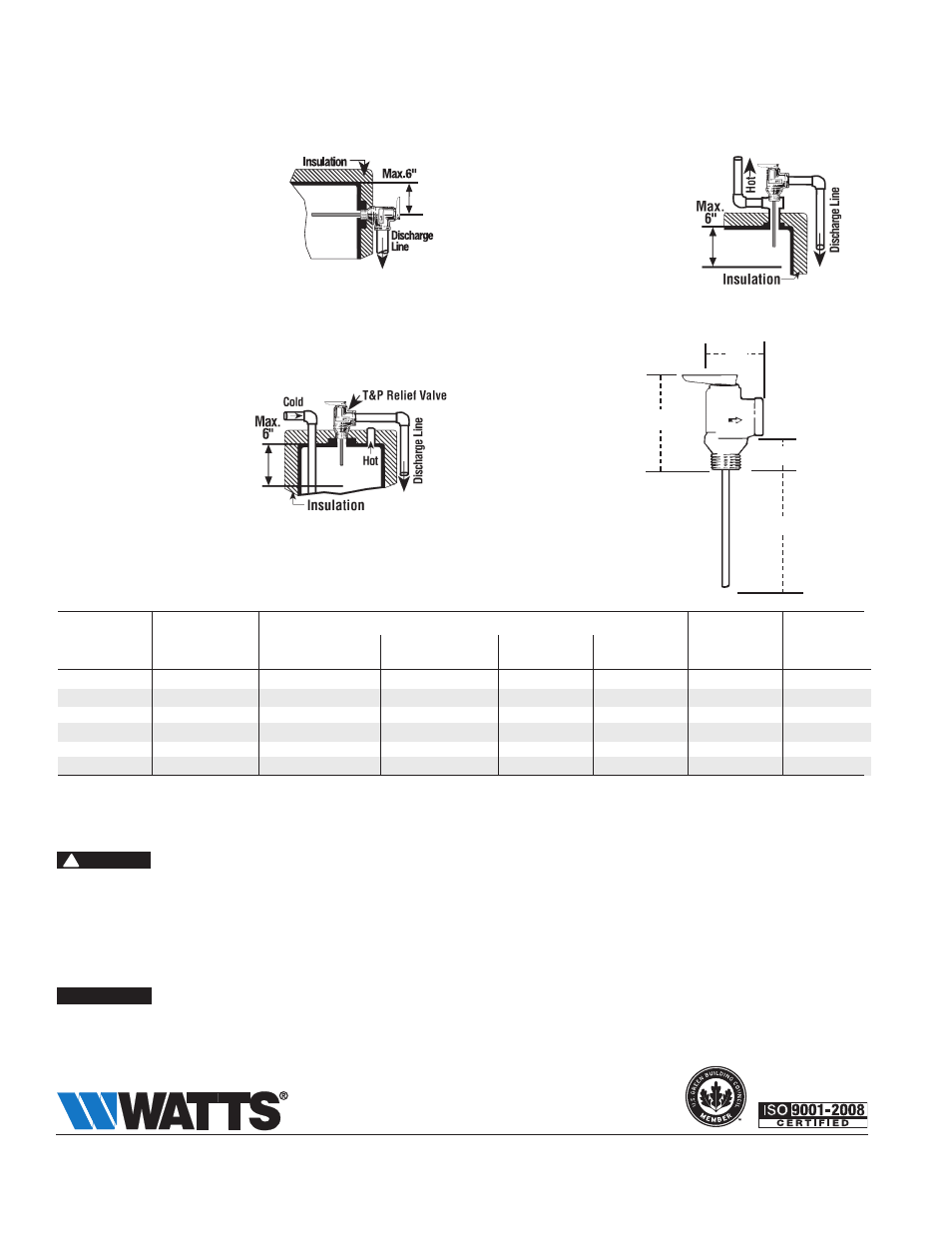
Direct Side Tapping
For External Flue Heaters
Use extra length extension thermo-
stat to extend into water storage
tank.
For Internal Flue Heaters
Use short or standard length
thermostat. Vertical discharge line
must be installed with its direction
downward.
Model
Size
diMeNSioNS
CSA
(DN)
A
B
D
T
Weight
Temp. Steam
in. mm in. mm
in.
mm
in.
mm
in.
mm
oz.
gm.
Rating
BTU/hr.
LF1L2 M7
1
⁄
2
15 1
3
⁄
4
43 3
1
⁄
2
89
7
⁄
8
22
2
50
10
284
15,000
LF1XL-4 M7
1
⁄
2
15 1
3
⁄
4
43 3
1
⁄
2
89
7
⁄
8
22
4
100
12
340
15,000
LF1XL-8 M7
1
⁄
2
15 1
3
⁄
4
43 3
1
⁄
2
89
7
⁄
8
22
8
203
16
454
15,000
LF10L-2 M7
3
⁄
4
20 1
3
⁄
4
43 3
1
⁄
2
89 1
1
⁄
8
29
2
50
10
284
80,000
LF100XL-4 M7
3
⁄
4
20 1
3
⁄
4
43 3
1
⁄
2
89 1
1
⁄
8
29 4 100 12 340 105,000
LF100XL-8 M7
3
⁄
4
20 1
3
⁄
4
43 3
1
⁄
2
89 1
1
⁄
8
29
8
203
14
397
105,000
A = overall width of the valve. B = overall height of the valve, with lever closed, not including thermostat element length. D = length of shank , from shoulder
under outlet orifice overhang to inlet orifice edge.
T = length of thermostat element, measured from inlet orifice edge to end of thermostat.
* 150psi set pressure
ReiNSPeCTioN oF T&P RelieF VAlVe: Temperature and Pressure Relief Valves should be reinspected AT leAST oNCe eVeRY TWo To FoUR YeARS
by a licensed plumbing contractor or authorized inspection agency, to insure that the product has not been affected by corrosive water conditions and to
insure that the valve and discharge line have not been altered or tampered with illegally. Certain naturally occurring conditions may corrode the valve or its
components over time, rendering the valve inoperative. Such conditions are not detectable unless the valve and its components are physically removed and
inspected. Do not attempt to conduct this inspection on your own. Contact your plumbing contractor for a reinspection to assure continuing safety.
FAilURe
To ReiNSPeCT THiS VAlVe AS diReCTed CoUld ReSUlT iN UNSAFe TeMPeRATURe oR PReSSURe BUild-UP WHiCH CAN ReSUlT iN SeRioUS
iNJURY oR deATH ANd/oR SeVeRe PRoPeRTY dAMAGe.
A relief valve functions in an emergency by discharging water. Therefore, it is essential that a discharge line be piped from the valve in order to carry the
overflow to a safe place of disposal. The discharge line must be the same size as the valve outlet and must pitch downward from the valve and terminate at
least 6"(152mm) above the floor drain where any discharge will be clearly visible. For 100DT discharge line consult your Watts agent.
Direct Top Tapping
For Heaters
Use standard or extra length
extension thermostat.
Alternate
Only when the tappings are
not provided
Use standard or extra length
extension thermostat.
ES-LF1L_LF1XL_LF10L_LF100XL 1310
© 2013 Watts
USA: Tel: (978) 688-1811 • Fax: (978) 794-1848 • www.watts.com
Canada: Tel: (905) 332-4090 • Fax: (905) 332-7068 • www.watts.ca
A Watts Water Technologies Company
WARNING
!
IMPORTANT
T
B
A
D