Watts SAN89 User Manual
Page 3
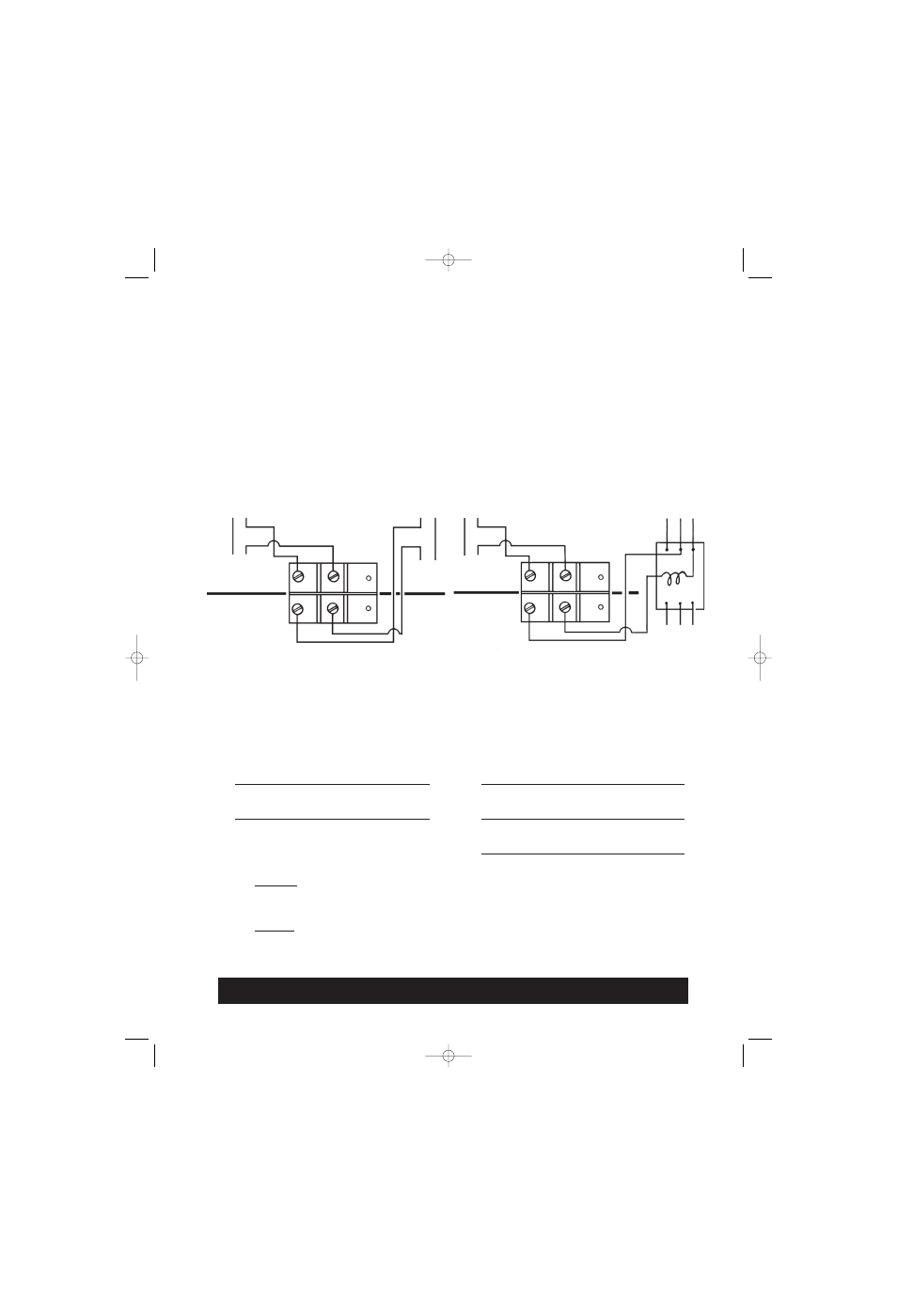
Wiring Diagrams For
Low Water Cut-offs
No. N89D, N101D, N93D, N193D, N50D, N501D
with "Dual" (Two) Switch Assembly
For independent line voltage burner service and for low (or high) voltage alarm, feed
valve or pump starter service. Alarm, feed valve or pump starter switch actuates just
b
be
effo
orre
e the burner switch cuts the firing.
For loads in excess of ratings or when a 3-phase burner motor is used, use either switch
as pilot to operate a relay or magnetic starter as shown under "Pilot Duty" above for
burner switch.
Incoming leads must be suitable for temperature rise of 90°C (194°F).
WARNING: DO NOT CONNECT TO AN ELECTRICAL LOAD IN EXCESS OF THE RATED
CAPACITY OF THE SWITCH.
Switch cuts off burner or stoker when water line drops approximately
3
⁄
8
" below center line. Switch alarm
circuit when used is closed just before burner cuts off.
CAUTION: "This switch mechanism is factory set for optimum performance, alteration may cause the
valve to malfunction and will invalidate the warranty.
ALWAYS CHECK THE CUT-OFF LEVEL BEFORE LEAVING THE JOB.
TOP
LINE
HI or LO
Voltage
(
)
HI or LO
Voltage
Alarm Feed
Valve or Pump
Starter
Service Switch
Closed Circuit
Burner Switch
Closed Circuit
LINE
Burner
Load
Norm
Open
Norm
Closed
Norm
Closed
Common
Common
Norm
Open
TOP
LINE
HI or LO
Voltage
(
)
HI or LO
Voltage
Alarm Feed
Valve or
Pump Starter
Service Switch
Closed Circuit
Burner Switch
Closed Circuit
LINE
Line
(Burner)
Norm
Open
Norm
Closed
Norm
Closed
Common
Common
Norm
Open
Motor Duty
AC
1
⁄
2
H.P.
1 Phase
110-120 volts
1 H.P.
1 Phase
220-240 volts
Pilot Duty
AC
15 Amps.
120, 240 volts
DC
1
⁄
2
Amps.
120 volts
Motor Duty
AC
1
⁄
2
H.P.
1 Phase
100-120 volts
1 H.P.
1 Phase
220-240 volts
Pilot Duty
AC
472 V.A.
120 volts
768 V.A.
240 volts
Alarm Circuit
AC
15 Amps.
120, 240 volts
DC
1
⁄
2
Amps.
120 volts
Relay
When Used For PILOT DUTY
When Used For
BURNER SWITCH and
ACCESSORY CIRCUITS
IS-N89.qxd 9/15/08 2:18 PM Page 3