Watts SAN89 User Manual
Page 2
No. N93S, N193S, N93D, N193D
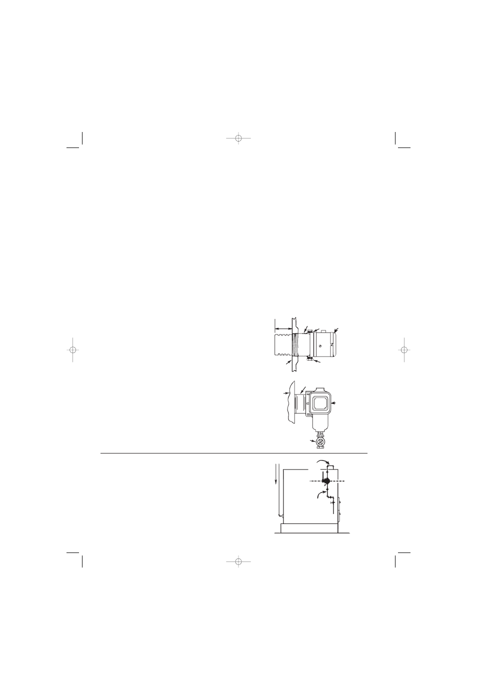
Attach cut-off to the boiler by screwing into the 2
1
⁄
2
" tapping provided,
make up tight with the "TOP" marking uppermost and the adjacent flat
edge of the square flange is exactly level. Before installing No. N93S,
N93D, be sure that there is a minimum distance of 2
1
⁄
4
" between the
inside of the boiler shell and any wall or other protrusion inside the boil-
er. (See Figure 1.) Maximum Steam Pressure 15 lbs.
No. N101S, N101D
Attach cut-off to boiler as in Fig. 2 using a 2
1
⁄
2
" close or space nipple
to suit installation requirements. Make up tight with float chamber lev-
elled in position shown. Attach drain valve. Maximum Steam Pressure
15 lbs.
No. N50S, N50D, N501S, N501D
Watts Series N50 and N501 are designed with a heavier float and bel-
lows construction for protection of hot water space heating boilers
against emergency low water conditions. Float chamber has 1" female
top and bottom connections, for equalizing pipe connection. (See
Figure 3). Maximum Boiler Pressure 50 lbs. @ 250°F.
For installation of N501, see Figure 2.
with Single Switch Assembly. (See Page 4)
with "DUAL" (Two) Switch Assembly. (See Page 3)
This line of cut-offs was designed for boilers where a 2
1
⁄
2
" pipe tapping is provided for the low water cut-off
and where space is limited by the boiler jacket. For boilers that do not have this tapping, use WATTS No.
N89S, N89D which is made for gauge glass connection.
Special Notice
Before leaving the job, it is recommended that the installation of the cut-off be checked under actual working conditions;
this will reveal any installation irregularities. To check, turn on switch to burner and if water in boiler is at or above
the water line, the cut-off will allow the burner to start. Now lower the water line by draining off water from
the boiler; if the cut-off is wired and installed correctly, the burner will shut off when the water level drops to
approximately
3
⁄
8
" below the normal water line.
Float chamber should be flushed at least once every month or more often to remove any accumulated sediment by
opening drain valve where installed or removing drain plug.
Insertion
Length
2
1
⁄
4
"
Marked Top
N93
N193
Level
Fig.1
N93
Only
Inside Boiler Shell
Drain Plug
Boiler
2
1
⁄
2
" Nipple
N101
N501
Fig. 2
Drain Valve
Supply
No. N50
Fig. 3
Equalizing
Pipe
Equalizing
Pipe
Cut-off Line
Built-in Cut-offs
No. N93S, N193S, N101S
No. N93D, N193, N101D
Instructions for Installing
IS-N89.qxd 9/15/08 2:18 PM Page 2