M ax. 6" i nsulatio n, D ischarge line, Direct side tapping – Watts LFLLL40XL User Manual
Page 2: For heaters with direct top tapping, General recommendations, Max. 6" insulation
ES-LFLL/LLL-40XL 1315
© 2013 Watts
USA: Tel: (978) 688-1811 • Fax: (978) 794-1848 • www.watts.com
Canada: Tel: (905) 332-4090 • Fax: (905) 332-7068 • www.watts.ca
A Watts Water Technologies Company
M ax. 6"
I nsulatio n
D ischarge
Line
Discharge Lin
e
Cold
Hot
T&P Relief
Valve
Max.
6"
Insulation
Max. 6"
(152mm)
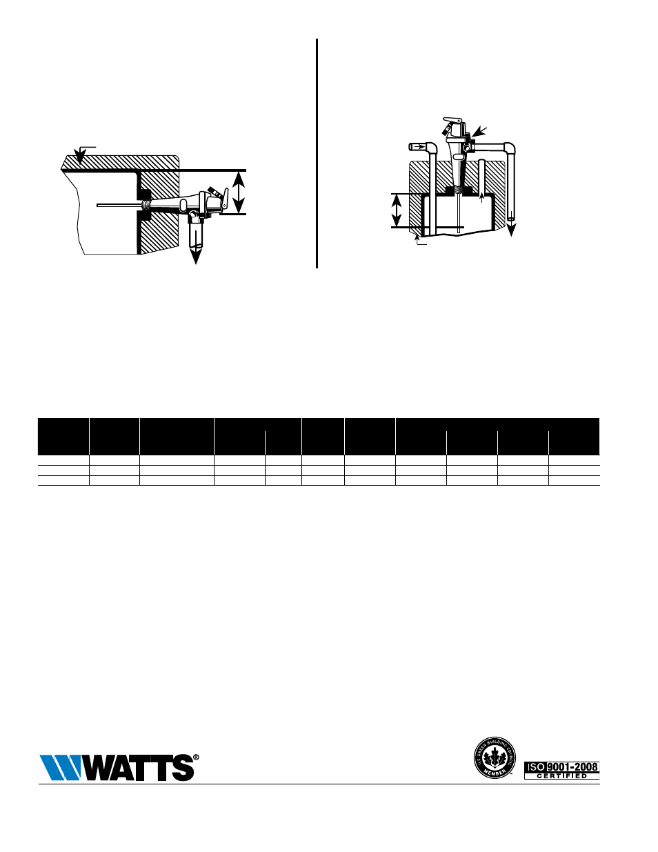
Direct Side Tapping
For External Flue Heaters
Use extra length extension thermostat to extend into water storage
tank.
For Internal Flue Heaters
Use short or standard length thermostat. Vertical discharge line must
be installed with its direction downward.
For Heaters with Direct Top Tapping
Use standard or extra length extension thermostat.
Max. 6"
(152mm)
General Recommendations
For gas, electric or oil-fired storage water heaters between 180,000 to 205,000 BTU/Hr. rating: Use 3⁄4" (20mm) Series 40 tested under ANSI
Z21.22 with ratings as certified and listed by CSA.
For gas or oil-fired storage water heaters between 205,000 and 500,000 BTU/Hr. rating and for compliance with applicable water heater label-
ing requirements: Use 1" (25mm) 40 Series tested under ANSI Z21.22 with ratings as certified and listed by CSA.
For the full range of high capacity temperature and pressure relief valves Series LF40, LF140, LF240, LF340 and LF342.
See ES-LF40, LF140, LF240, LF340.
ModeL
InLet X
outLet (In.)
therMostat Length
(In.) (BeLow InLet
thread)
dIMensIons (In.)
weIght
LBs.
Csa teMp.
steaM ratIng
Btu/hr
**asMe pressure steaM ratIng Btu/hr
heIght (Less
therMostat)
wIdth
@75psI set
pres.
@100psI set
pres.
@125psI set
pres.
@150psI set
pres.
LFLL40XL
3
⁄
4
M x
3
⁄
4
F
3
1
⁄
2
5
5
⁄
8
2
5
⁄
8
1
1
⁄
2
205,000
777,600
997,600
1,217,600
1,437,600
LFLLL40XL
3
⁄
4
M x
3
⁄
4
F
5
7
5
⁄
8
2
5
⁄
8
2
205,000
777,600
997,600
1,217,600
1,437,600
LFLL40XL
1M x 1F
3
6
1
⁄
2
2
3
⁄
4
2
500,000
1,155,000
1,481,000
1,808,000
2,134,000
M= Male
F=Female
**ASME capacities are steam pressure ratings and do not reflect the CSA temperature relieving capacity of the valves for selection purposes.
Temperature and Pressure Relief Valves should be inspected AT LEAST ONCE EVERY TWO TO FOUR YEARS, and replaced, if necessary, by
a licensed plumbing contractor or qualified service technician, to ensure that the product has not been affected by corrosive water conditions
and to ensure that the valve and discharge line have not been altered or tampered with illegally. Certain naturally occurring conditions may cor-
rode the valve or its components over time, rendering the valve inoperative. Such conditions can only be detected if the valve and its compo-
nents are physically removed and inspected. Do not attempt to conduct an inspection on your own. Contact your plumbing contractor for a
re-inspection to assure continuing safety.