Watts DETA User Manual
Series eta and deta, Asme code expansion tank
IS-ETA/DETA
Series ETA and DETA
ASME Code Expansion Tank
Installation Instructions
Warnings
• This Expansion Tank is designed and intended for water storage at maximum pres-
sure and maximum temperature as indicated on the nameplate. Any use other than
for water or at a sustained or instantaneous pressure in excess of listed rating is
UNSAFE and may cause property damage, serious bodily injury or result in death.
• This Expansion Tank, like all Expansion Tanks, may eventually leak. Do not install
without adequate drainage provisions where water flow will cause damage.
• Improper installation, adjustment, alteration, service or maintenance may cause
property damage, serious bodily injury or death. Read instructions completely before
proceeding with installation.
• Only qualified personnel should install or service this equipment in accordance with
local codes and ordinances.
• The manufacturer of this tank does not accept any liability or other responsibility for
personal injury or property damage resulting from improper use, installation or opera-
tion of this tank or the system of which it is a part.
Important!
• A Pressure Relief Valve sized and installed in accordance with Local Codes
must be incorporated in the system. In those systems requiring a combined
Temperature and Pressure Safety Relief Valve, the Temperature and Pressure
Safety Relief Valve should be sized and installed in accordance with Local Codes.
• Never plug a Safety Relief Valve.
1. Prior to beginning installation, visually inspect the tank for damage which may have
occurred during transit.
2. Determine the system pressure.
3. Prior to installation of the tank in the system the tank must be pre-charged to the
system pressure as determined in Step 2.
To pre-charge tank:
A. Remove pipe plug covering the valve enclosure.
B. Check and adjust the charge by adding or releasing air (Oil and water free com-
pressed air or nitrogen gas may be used.)
C. After adjusting air pressure, test air valve for leakage, (Shcrader type tire valve
core may be used for replacement.)
D. Replace pipe plug.
4. Set tank in place and connect system piping using isolation valve(s) and drain.
Caution: Do not loosen nuts on cover plate - This will result in loss of pre-charge. Cover
plate must not be removed until the air pressure in the tank has been bleed to zero
gauge pressure. (Model ET-RA only)
5. Purge air from system prior to placing tank into operation. When filling the system
with water, open valves to tank to ensure any water or air remaining in the bladder
from factory testing is displaced prior to placing the tank in operation.
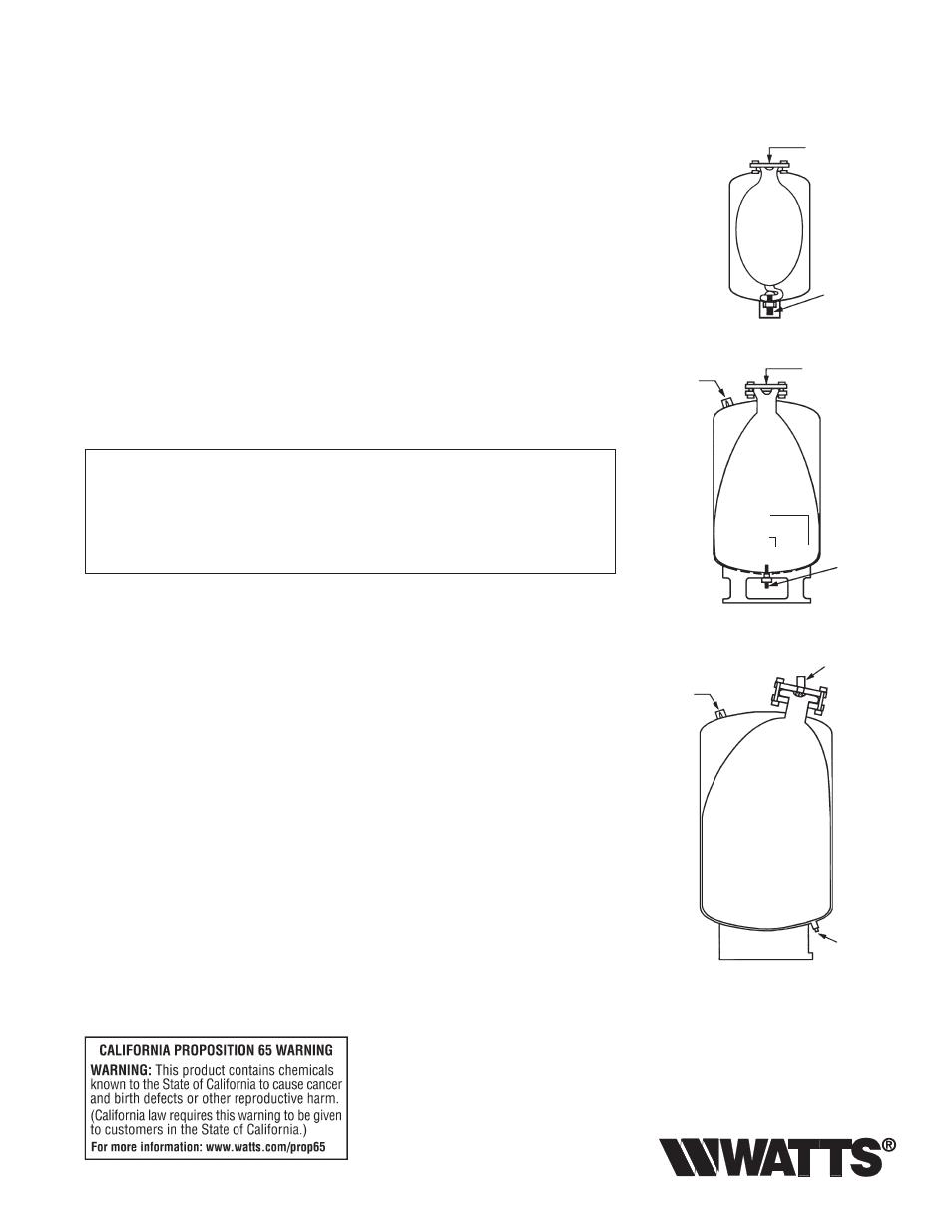
Note: Model ET-RA 85 through 800 - These tanks have both top and bottom access to
the bladder. It is recommended that only the bottom connection be used for connec-
tion to the system. Top connections may be used for gauges, relief valves, etc.
6. Any connection not used must be plugged and checked for leakage.
Air Charging
Valve
System
Connection
Air Charging
Valve
System
Connection
System
Connection
Air Charging
Valve
System
Connection
System
Connection
BLADDER
BLADDER
BLADDER