General recommendations, Direct side tapping, For heaters with direct top tapping – Watts N241X User Manual
Page 2
Thermostat
Inlet X
Length (in.)
Dimensions (in.)
CSA
Outlet
(Below Inlet
Height
Weight
Temp. Steam
**ASME PRESSURE STEAM RATING BTU/HR
Model
(in.)
thread)
(Less Thermostat)
Width
Lbs.
Rating BTU/HR
@75psi set pres. @100psi set pres. @125psi set pres. @150psi set pres.
40L-3
3
⁄
4
M x
3
⁄
4
F
3
5
5
⁄
8
2
5
⁄
8
1
3
⁄
4
180,000
777,600 997,600 1,217,600
1,437,600
40XL-5
3
⁄
4
M x
3
⁄
4
F
5
5
5
⁄
8
2
5
⁄
8
1
3
⁄
4
205,000
777,600 997,600 1,217,600
1,437,600
40XL-8
3
⁄
4
M x
3
⁄
4
F
8
5
5
⁄
8
2
5
⁄
8
1
3
⁄
4
205,000
777,600 997,600 1,217,600
1,437,600
140S-3
3
⁄
4
F x
3
⁄
4
F
3
5
5
⁄
8
2
5
⁄
8
1
3
⁄
4
180,000
777,600 997,600 1,217,600
1,437,600
140X-5
3
⁄
4
F x
3
⁄
4
F
5
5
5
⁄
8
2
5
⁄
8
1
3
⁄
4
205,000
777,600 997,600 1,217,600
1,437,600
140X-8
3
⁄
4
F x
3
⁄
4
F 8
5
5
⁄
8
2
5
⁄
8
1
3
⁄
4
205,000
777,600 997,600 1,217,600
1,437,600
40L-2
1M x 1F
2
6
1
⁄
4
2
3
⁄
4
2
1
⁄
4
450,000
1,155,000
1,481,000
1,808,000
2,134,000
40XL-4
1M x 1F
4
6
1
⁄
4
2
3
⁄
4
2
1
⁄
4
500,000
1,155,000
1,481,000
1,808,000
2,134,000
40XL-7
1M x 1F
7
6
1
⁄
4
2
3
⁄
4
2
1
⁄
4
500,000
1,155,000
1,481,000
1,808,000
2,134,000
*140S-3
1F x 1F
3
5
1
⁄
2
3
2
1
⁄
4
570,000
1,670,000
2,140,000
2,610,000
3,085,000
*140X-6
1F x 1F
6
5
1
⁄
2
3
2
1
⁄
4
670,000
1,670,000
2,140,000
2,610,000
3,085,000
*140X-9
1F x 1F
9
5
1
⁄
2
3
2
1
⁄
4
670,000
1,670,000
2,140,000
2,610,000
3,085,000
*N240X-6
1F x 1F
6
6
5
⁄
8
3
3
⁄
8
2
3
⁄
4
730,000
2,195,000
2,817,000
3,438,000
4,059,000
*N240X-9
1F x 1F
9
6
5
⁄
8
3
3
⁄
8
2
3
⁄
4
730,000
2,195,000
2,817,000
3,438,000
4,059,000
*N241X-5 1
1
⁄
4
M x 1F
5
6
5
⁄
8
3
3
⁄
8
2
3
⁄
4
730,000
2,195,000
2,817,000
3,438,000
4,059,000
*N241X-8 1
1
⁄
4
M x 1F
8
6
5
⁄
8
3
3
⁄
8
2
3
⁄
4
730,000
2,195,000
2,817,000
3,438,000
4,059,000
*340-3 1
1
⁄
2
F x 1
1
⁄
2
F
3
9
3
⁄
4
4
1
⁄
2
7 1,150,000
3,450,000
4,426,000
5,403,000
6,379,000
*340X-8 1
1
⁄
2
F x 1
1
⁄
2
F
8
9
3
⁄
4
4
1
⁄
2
8 1,150,000
3,450,000
4,426,000
5,403,000
6,379,000
*342-3
2 M 1
1
⁄
2
F
3
9
3
⁄
4
4
1
⁄
2
7 1,150,000
3,450,000
4,426,000
5,403,000
6,379,000
*342X-8
2 M x 1
1
⁄
2
F
8
9
3
⁄
4
4
1
⁄
2
8 1,150,000
3,450,000
4,426,000
5,403,000
6,379,000
*Standardly furnished with stainless steel thermostat tube.
M = Male
F = Female
**ASME capacities are steam pressure ratings and do not reflect the CSA temperature relieving capacity of the valves for selection purposes.
†LL40XL and LLL40XL valves with extended inlet shanks should be used for water heaters that have extra thick insulation, Ask for ES-LL/LLL-40XL.
General Recommendations
†
For gas, electric or oil-fired storage water heaters between 180,000 to
205,000 BTU/Hr. rating: Use
3
⁄
4
" (20mm) Series 40, 140 tested under
ANSI Z21.22 with ratings as certified and listed by CSA.
For gas or oil-fired storage water heaters between 205,000 and 730,000
BTU/Hr. rating and for compliance with applicable water heater labeling
requirements: Use 1" (25mm) 40, 140, N240 Series tested under ANSI
Z21.22 with ratings as certified and listed by CSA.
For installations of gas or oil-fired hot water supply boilers over 730,000
BTU/Hr. output heating domestic water and for steam coil storage water
heaters: Use Series 340, 342 tested under ANSI Z21.22 with rating as
certified and listed by CSA.
SPECIAL MODEL: No. 340X-8 M4Z 1
1
⁄
2
" (40mm) size only. Pressure setting
175psi (5.2 bar). Temp. 210°F (99°C). Certified by CSA only.
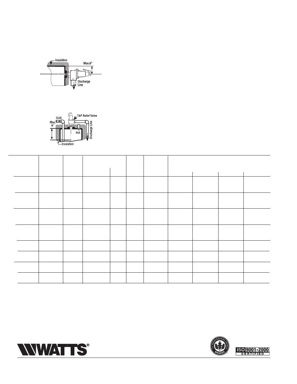
Direct Side Tapping
FOR EXTERNAL FLUE HEATERS
Use extra length extension thermostat to extend into water storage tank.
FOR INTERNAL FLUE HEATERS
Use short or standard length thermostat. Vertical discharge line must be
installed with its direction downward.
For Heaters with Direct Top Tapping
Use standard or extra length extension thermostat.
Temperature and Pressure Relief Valves should be inspected AT LEAST ONCE EVERY THREE YEARS, and replaced, if necessary, by a licensed
plumbing contractor or qualified service technician, to ensure that the product has not been affected by corrosive water conditions and to ensure that the
valve and discharge line have not been altered or tampered with illegally. Certain naturally occurring conditions may corrode the valve or its components
over time, rendering the valve inoperative. Such conditions can only be detected if the valve and its components are physically removed and inspected.
Do not attempt to conduct an inspection on your own. Contact your plumbing contractor for a reinspection to assure continuing safety.
Max. 6"
(152mm)
ES-40,140,240,340 0927
© 2009 Watts
USA: 815 Chestnut St., No. Andover, MA 01845-6098; www.watts.com
Canada: 5435 North Service Rd., Burlington, ONT. L7L 5H7; www.wattscanada.ca
A Watts Water Technologies Company