Test procedure for pressure type vacuum breaker, Test procedure for double check valve assembly – Watts TK-99D User Manual
Page 3
High
(red)
Test
Cock
No. 2
Test Cock
No. 1
Test Procedure for Pressure Type Vacuum
Breaker
Note: For both of the following tests the test kit must be held at
the same level as the assembly being tested.
A. Before starting test all needle valves must be closed.
B. Flush test cock #2 and #1.
Turn Test Kit On
Test No. 1 - Air Inlet
Requirement: Air inlet must start to open when down stream
pressure is 1.0psi or above.
Step 1 Remove two screws on top of hood and remove
hood.
Step 2 Install hose between test cock No. 2 and connection
“A” on high side(red) on test kit.
Step 3 Open test cock No. 2 and needle valve “A” high side
(red) on test kit.
Step 4 Open vent needle valve and bleed air from hose.
Then close vent valve.
Step 2 Close test cock No. 4. Disconnect bypass hose (yel-
low) at test cock No. 4. Close vent needle valve.
Step 3 Open needle valve “B” and vent or bypass needle
valve, bleeding to atmosphere, then closing needle
valve “B” restores the system to a normal static
condition.
Step 4 Observe the pressure differential gauge. If there is a
decrease in the indicated value, the No. 1 check valve
is reported as leaking.
Test No. 4 - Pressure Differential Relief Valve
Purpose: To test Operation of pressure differential relief valve
Requirements: The pressure differential relief valve must operate
to maintain the “zone” between the two check valves at least
2psi less than the supply pressure.
Step 1 Close vent or bypass needle valve
Step 2 Open needle valve “A” high side.
Step 3 Open needle valve “B” low very slowly until the differ-
ential reading starts to drop.
Step 4 Hold the valve at this position and observe the read-
ing at the moment the first discharge is noted from the
relief valve. Record this as the opening differential
pressure of the relief valve. Note: it is important the
differential reading drop slowly.
Step 5 Close test cocks Nos. 2 and 3.
Step 6 Use bypass hose (yellow) to relieve pressure from test
kit by opening needle valve “A”, “B”, and vent needle
valve.
Step 7 Remove all test equipment and open No. 2 shutoff
valve of the device.
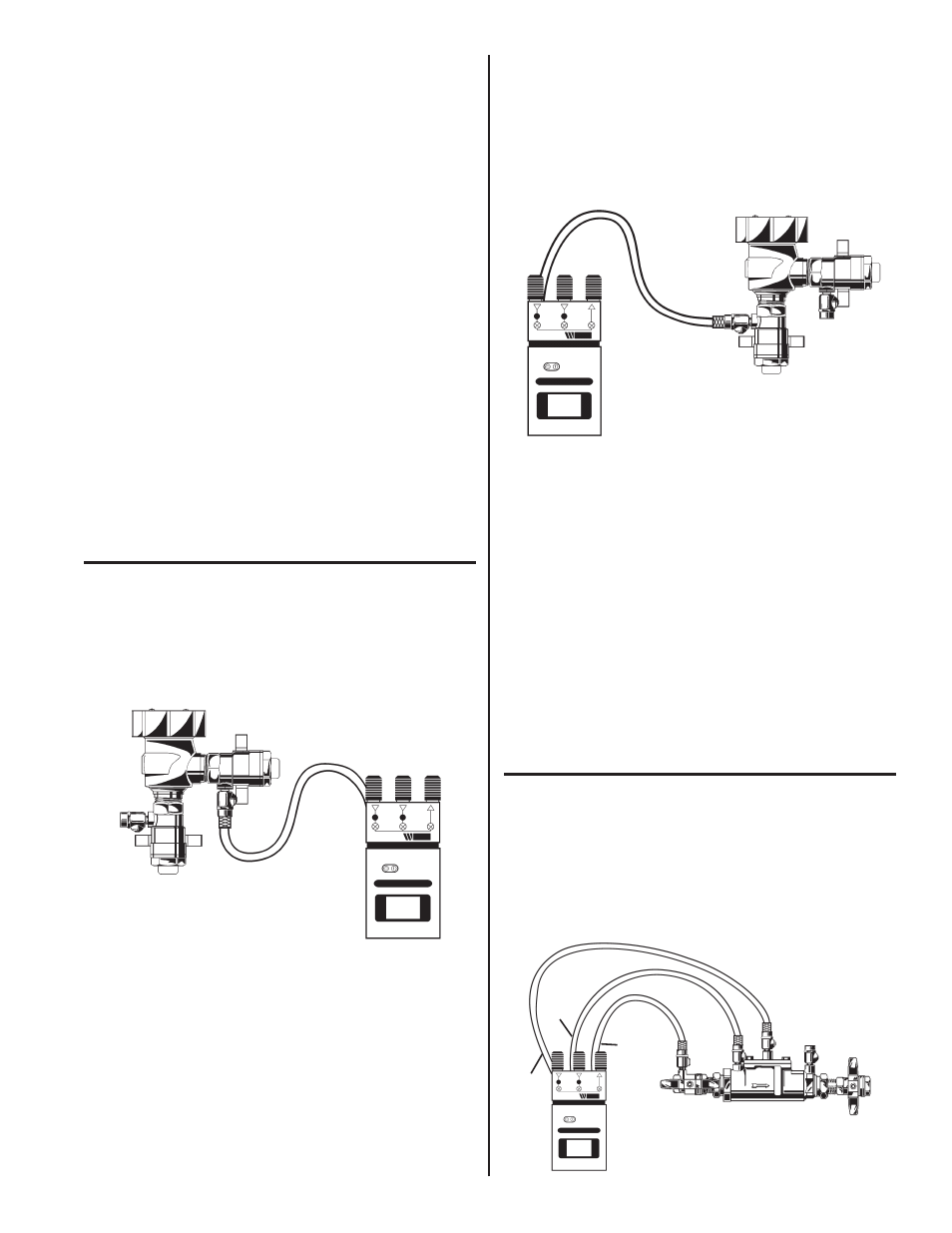
Test No. 1
800M4QT shown
Test No. 2
800M4QT shown
High
(red)
Test Cock
No. 1
Test Cock
No. 2
Test No. 2 - Test check Valve Pressure Drop
Requirement: Supply pressure drop must be 1.0 PSID or more
when water flow stops from test cock No. 2.
Step 10 Install hose between test cock No.1 and connection
“A” high side (red) on test kit.
Step 11 Open test cock No. 1 and bleed valve by opening
vent needle valve. Bleed air from hose then shut vent
needle valve
Step 12 Close shutoff valve #1.
Step 13 Open test cock No. 2. When flow of water out of test
cock No. 2 stops, the differential reading is the pres-
sure drop reading.
Step 14 Close test cock No. 1 and test cock No. 2. Remove
hoses.
Step 15 Replace hood and two screws on top of hood.
Note: After test, all valves must be open and hoses removed to
prevent damage to test kit.
Step 5 Close shutoff valve No. 2 then shutoff valve No. 1.
Step 6 Slowly open vent needle valve just as air inlet opens.
Record differential pressure.
Step 7 Close test cock No. 2 and remove hose.
Step 8 Close vent needle valve.
Step 9 Open shutoff valve No. 1.
Test Procedure for Double Check Valve
Assembly
A.
Before starting test, all needle valves on test kit must be
closed.
B.
Flush test cocks before test.
Turn Test Kit On
Test No. 1
High
(red)
Low
(blue)
Bypass
(yellow)
007 shown
3