Iii. valve installation, E. installation considerations, F. drain requirements – Watts PWBWIRON User Manual
Page 5
5
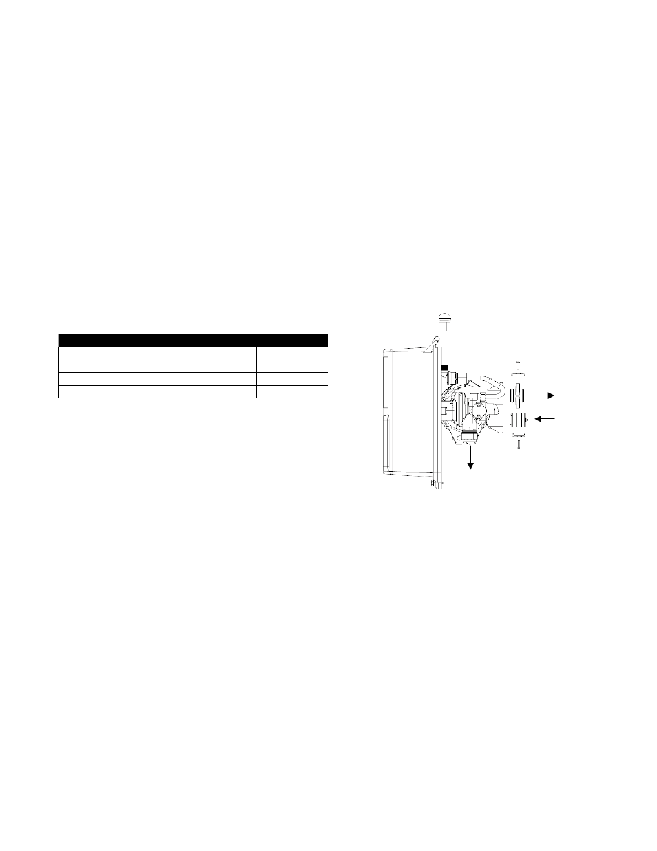
Figure 4
E. Installation Considerations
Consider the following points when determining where to install the
filter:
• Place the system as close as possible to a sewer drain.
• Do not install the filter where it would block access to the water
heater, or access to the main water shutoff, water meter, or electri-
cal panels.
• Install the filter in a place where water damage is least likely to oc-
cur if a leak develops.
• A 120VAC electrical outlet is needed to plug in the transformer.
• Always connect the system to the main water supply pipe before
the water heater.
• Install the system where it will not be subject to temperatures
outside of the limits stated in the Specification Section or to direct
sunlight.
F. Drain Requirements
The drain systems these filters are plumbed into must be able to
accept the drain rates listed below. The well or water supply must
be capable of maintaining a 30 psi minimum feed water pressure,
continuously, at these drain flow rates.
MoDEl
TAnK sIzE
DrAIn rATE
PWBWIRON1
9" x 48", 1 cubic ft.
7 gpm
PWBWIRON15
10" x 54", 1.5 cubic ft.
8 gpm
PWBWIRON2
12" x 52", 2 cubic ft.
12 gpm
PWBWIRON3
13" x 65", 3 cubic ft.
15 gpm
III. Valve Installation
1. Turn off gas or electric supply to the water heater.
2. Close the feed water valve to the plumbing system. Then
relieve the pressure in the plumbing by opening the hot and
cold water faucets.
3. Cut the pipes at the installation point. Use a drain pan to catch
any spillage that results.
4. Move the filter system into installation position.
• Be sure the installation point is downstream of the bladder tank
and irrigation system if this system is being installed on a well.
• The installation surface must be strong enough to support the
weight of the system once it is placed into operation.
5. Plumb INLET and OUTLET connections to and from the filter.
• Be sure the incoming water supply is directed to the INLET port
of the valve.
• The valve body of the control is marked with arrows indicating
the proper flow direction.
• Connections are illustrated below in Figure 4 (shown without
bypass and yoke) and Figure 5 (bypass piping detail).
6. Connect and route the valve drain line using rigid piping or
hose. Use the same size plumbing for the drain line as the fit-
ting provided for the drain connection. The smallest units have
a
1
⁄
2
" connection, the medium sized units have a
3
⁄
4
" connec-
tion, and the largest units have a 1" connection. It is important
to use the same size plumbing as the connection to ensure
proper backwash flow.
Note: Leave an air gap of at least 1
1
⁄
2
" between the end of the
drain plumbing and the drain point.
CAUTION: If making a soldered copper installation, do all
sweat soldering before connecting pipes to the bypass valve.
Torch heat will damage plastic parts.
CAUTION: When turning threaded pipe fittings onto plastic
fittings, use care not to cross-thread or overtighten.
CAUTION: Use PTFE tape on all external pipe threads. Do not
use pipe joint compound.
CAUTION: Support inlet and outlet plumbing in some manner
(use pipe hangers) to keep the weight off of the control valve
drain, bypass, and plumbing yoke points of connection.
Outlet
Inlet
Drain
Drain
Inlet
Outlet