Watts LF7 User Manual
Series lf7, Lead free, Dual check valves
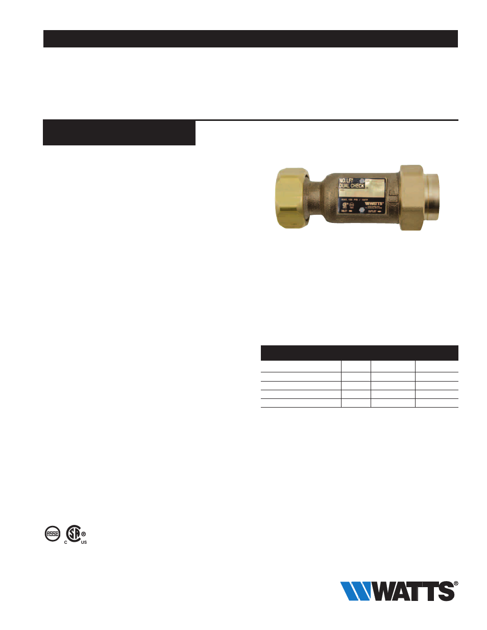
Series LF7
Dual Check Valves
LF7 Sizes: 1
1
⁄
4
" (32mm)
LF7C Sizes:
3
⁄
8
" (10mm)
Series LF7 Dual Check Valves are designed for non-health
hazard residential water system containment and continu-
ous pressure applications, such as the drinking water supply
service entrance or individual outlets. Series LF7 uses two
compact replaceable check modules and is installed imme-
diately downstream of the residential water meter. The LF7
features Lead Free* construction to comply with Lead Free*
installation requirements.
Features
• Can be installed vertically or horizontally
• Available with combination of inlet/outlet sizes, types or
thread and end connection including retrofit compression
fittings and hose connections
• Can be installed in many piping configurations and with a
wide range of meter horns, copper setters and meter boxes
Specifications
The dual check backflow preventer shall meet the domestic
requirements of ANSI/ASSE Standard 1024, and bear the
seal of approval. It shall have a cast body and include not
less than one union, with the union nut drilled to accept a
tamper-proofing lock wire. A brass identification tag indicat-
ing direction of flow shall be securely attached to the valve
body by corrosion-resistant mechanical fasteners. The Lead
Free* Dual Check Valve shall comply with state codes and
standards, where applicable, requiring reduced lead content.
The dual check shall be Watts Series LF7. (Please select the
model best suited to your application.)
Pressure - Temperature
Temperature Range: 33˚F – 180˚F (0.5˚C-82˚C) continuous
Maximum Working Pressure: 150psi (10.3 bar)
Approvals
For Light Commercial and Residential Applications
ES-LF7
Job Name –––––––––––––––––––––––––––––––––––––––––––
Contractor ––––––––––––––––––––––––––––––––––––––––––––
Job Location –––––––––––––––––––––––––––––––––––––––––
Approval –––––––––––––––––––––––––––––––––––––––––––––
Engineer –––––––––––––––––––––––––––––––––––––––––––––
Contractor’s P.O. No. ––––––––––––––––––––––––––––––––––
Approval –––––––––––––––––––––––––––––––––––––––––––––
Representative ––––––––––––––––––––––––––––––––––––––––
LF7
1024
B64.6
Watts product specifications in U.S. customary units and metric are approximate and are provided for reference only. For precise measurements,
please contact Watts Technical Service. Watts reserves the right to change or modify product design, construction, specifications, or materials with-
out prior notice and without incurring any obligation to make such changes and modifications on Watts products previously or subsequently sold.
* When ordering Series LF7 Valves with Meter Thread Con-
nections, be sure to order connection size one size
larger than meter thread. Example:
Meter Size
Order
1" (25mm)
1
1
⁄
4
" (32mm)
* The wetted surface of this product contacted by consumable
water contains less than 0.25% of lead by weight.
LEAD FREE
*
Series 7: Inlet/Outlet Connections – Types available, ordering
code, sizes available.
ConneCTIon
ConneCTIon
SIzeS avaILaBLe
Type
Code
in.
mm
National Pipe Thread Female
2
3
⁄
8 ,
1
1
⁄
4
10, 32
National Pipe Thread Male
3
1
1
⁄
4
32
Meter Thread Female*
4
1
1
⁄
4
32
Female Meter Thread (Swivel)
10
1
1
⁄
4
32
Standards
Complies with Buy America Act (BAA 1933) and The Ameri-
can Recovery and Reinvestment Act (ARRA 2009).