Dimensions — weights, Typical installations, Gas capacity – Watts 210-5 User Manual
Page 2
ES-210-5 0531
© Watts Regulator Company, 2005
USA: 815 Chestnut St., No. Andover, MA 01845-6098; www.wattsreg.com
Canada: 5435 North Service Rd., Burlington, ONT. L7L 5H7; www.wattscanada.ca
A
D
B
C
Dimensions — Weights
“Alternate” Only When The Tappings Are Not Provided
“Alternate” Only When The Tappings Are Not Provided
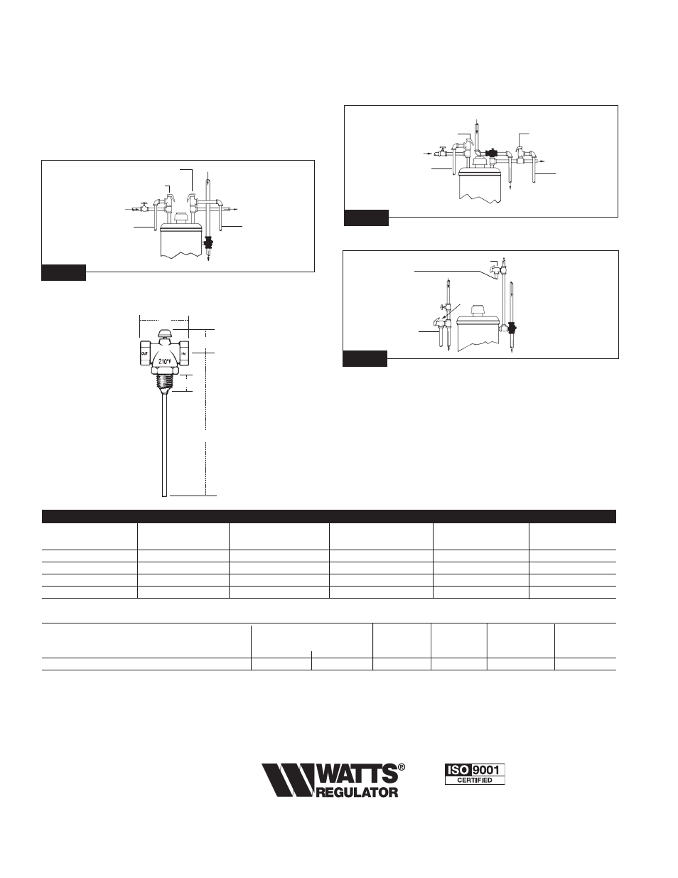
Fig. 2
Fig. 3
Typical Installations
Installation: The gas shutoff valve must be installed so that the ther-
mostat is immersed in the water within the upper 6" of the tank DO
NOT INSTALL IN COLD WATER LINE.
Note: The installation of a separate pressure relief valve is necessary for
installations using gas shutoffs.
Pressure Relief
Valve Alternate
Installation
Gas From
Supply
Cold
Drain Tube
Hot
Drain Tube
Series
210-5
Gas To
Burner
Pressure Relief
Valve Alternate
Installation
Gas From
Supply
Cold
Drain Tube
Pressure Relief Valve
Hot
Drain Tube
Series
210-5
Gas To Burner
To Bottom Supply
Pressure Relief Valve
Pressure Relief Valve
Pressure Relief Valve
Alternate Installation
Direct side Tapping
Fig. 1
Gas From
Supply
Cold
Drain Tube
Hot
Drain Tube
Series 210-5
Gas To Burner
MODEL
DIMENSIONS
WEIGHT
A
B
C
D
in.
mm
in.
mm
in.
mm
in
mm
lbs
kgs.
210-5 M2
2
1
⁄
2
64
1
1
⁄
8
29
8
203
7
/
8
22
1.0
0.45
L210-5 M2
2
1
⁄
2
64
1
1
⁄
8
29
7
13
/
16
198
1
7
/
8
48
1.0
0.45
LL210-5 M2
2
1
⁄
2
64
1
1
⁄
8
29
8
5
/
16
211
2
3
/
8
60
1.0
0.45
LLL210-5 M2
2
1
⁄
2
64
1
1
⁄
8
29
8
13
/
16
224
2
7
/
8
73
1.0
0.45
Models
BTU/HR Ratings
Connections
Natural
L.P.
M.F.G. and L.P.
Tank
Gas
Gas
Gas
Gas Air Mixtures
Mixed Gases
210-5 M2, L210-5 M2, LL210-5 M2, LLL210-5 M2
3
⁄
4
" male
1
⁄
2
" female
150,000
243,000
77,400
125,750
Gas Capacity
C.S.A. listed ratings of this valve are:
For use with natural gas
150,000 BTU/hr.
For use with liquified petroleum gas
243,000 BTU/hr.
NOTE: See C.S.A. directory for adjustment factors when used
with manufactured, mixed and L.P. gas-air mixtures.