Figure 13, Connecting the adapter box, Figure 14 – Metrohm 856 Conductivity Module User Manual
Page 30: Figure 13 connecting the adapter box
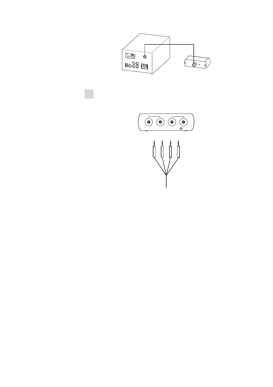
3.5 Connecting sensors
■■■■■■■■■■■■■■■■■■■■■■
22
■■■■■■■■
856 Conductivity Module
USB 1
USB 2
MSB 1
MSB 2
MSB 3
MSB 4
Made by Metrohm Herisau Switzerland
Controller
100 -200 V
f = 50 - 60 Hz
P = 45 W
Cond. Cell
Typ
Nr.
Metrohm
Switzerland
Figure 13
Connecting the adapter box
2 Plug the black plugs of the conductivity measuring cell into the black
Cond. Cell sockets and the red plugs into the red Pt 1000 sockets
on the front of the adapter box.
6.2103.160
Metrohm
Cond. cell
Pt 1000
Figure 14
Connecting the conductivity measuring cell to the
adapter box
During conductivity measurements, take care to ensure that
■
the measuring cell is positioned in such a way that the upper side
openings are completely immersed in the liquid.
■
no air bubbles adhere to the Pt rings or Pt platelets. Air bubbles pres-
ent inside the measuring cell can be removed by swinging back and
forth and by tapping.
■
the conductivity measuring cell is not so deeply submerged in the solu-
tion that it becomes damaged when the stirring bar is used to mix the
solution.
■
the magnetic stirrer is switched off during the measurement.