2 connecting the mcs, Connecting the mcs, Figure 15 – Metrohm 940 Professional IC Vario ONE/SeS/PP/Prep 1 User Manual
Page 55
■■■■■■■■■■■■■■■■■■■■■■
3 Installation
940 Professional IC Vario ONE/SeS/PP/Prep 1 (2.940.1510)
■■■■■■■■
45
ymer membrane. At the same time, the vacuum pump generates a vac-
uum and draws in the air from the outside. The pressure and concentra-
tion difference this creates in the degassing cell relative to inside the capil-
lary causes the CO
2
to be diffused out of the eluent stream. The ambient
air is drawn in by a CO
2
adsorption cartridge that filters out the CO
2
.
3.15.2
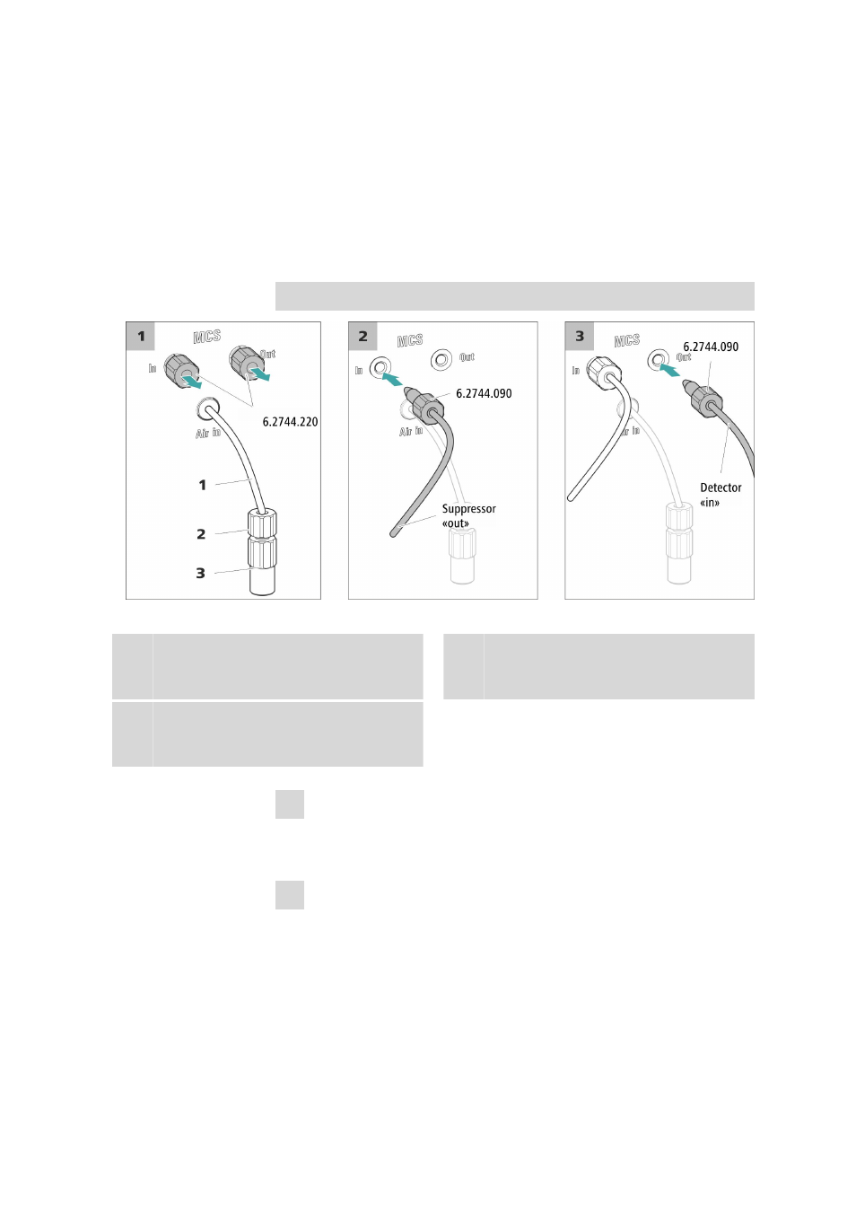
Connecting the MCS
The MCS is connected between the suppressor and the detector.
Connecting the MCS
Figure 15
Connecting the MCS
1
Air aspiration capillary
For drawing in air with low CO
2
content (via
the CO
2
adsorption cartridge).
2
Pressure screw, short (6.2744.070)
Installed on the air aspiration capillary.
3
Luer coupling (6.2744.120)
Mounted on the air aspiration capillary with
a pressure screw (6.2744.070).
1 Removing the threaded stoppers
Remove and keep the two threaded stoppers (6.2744.220) from the
input and output of the MCS.
2 Connection from the suppressor
Use a long pressure screw (6.2744.090) to connect the capillary
labeled out to the input of the of the MCS (labeled In).