Attach electric equipment to center frame – DJI S800 EVO User Manual
Page 8
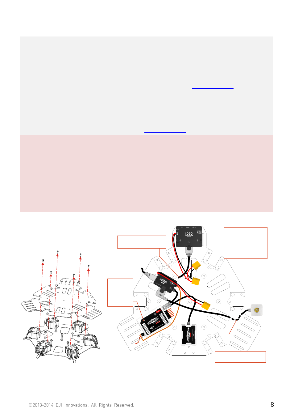
Attach Electric Equipment to Center Frame
1.
(Fig.1)Remove the screws in the bottom board.
2.
(Fig.2)Attach the IMU module into IMU position in the center frame. Ensure the IMU casing is out of
touching the top board edge, as vibration can cause IMU mal-function.
3.
(Fig.2)Please attach DJI Autopilot System parts onto the bottom board (not including GPS modules.
4.
(Fig.2)Connect the Autopilot System and receiver. Please refer to DJ
r details.
5.
(Fig.3)Please fix all the screws to bottom board, and use adequate thread locker.
6.
(Fig.4)Attach the GPS Fixed Seat to the top board (near to the M3), then mount the GPS Module to the
GPS Fixed Seat with a bracket.
7.
Configure Autopilot System. Please refer to DJ
Note:
(1)
Make sure to mount the IMU module at the IMU position first, and the mount orientation is correct.
(2)
Mount the GPS with a bracket, to avoid interference from center frame power board.
(3)
Make sure the USB port of the M.C. is pointing outwards for easy access.
(4)
Please wire neatly. Make sure the wires will not be cut by the edge of frames.
(5)
Install the screws with appropriate strength to prevent damage threads.
(6)
Watch out clamping fingers when folding the GPS Bracket.
To GIMBAL Lead
To the CAN Port of
GPS/Compass Module
You can attach the LED
Module to the support
tube.
Note: Risk of wire cut
off by the Retracting
Mechanism.
GPS/Compass
Module
Micro-USB
Port faces
outwards for
connection
convenience
Receiver
(D-BUS)
You can wire the LED
through the bottom board
To PM Lead
Fig.1 Remove the screws Fig.2 Attach the Autopilot System