Sensor docking station, Sensor diagram, Pwr oxygen – Bully Dog 40430 GT for Hemi Plus User Manual
Page 61
Typical types of sensors that can be used by the different docks or ports
P1-P2
(pyro 1 and 2)
• Bully Dog Type K
Thermocouple
AN 1-AN 3
(Analog 1-32)
• Manifold Pressure
• Oil Pressure
• Barometer
• Other Sensors with
Three Wire Five Volt
F IN
(Frequency IN)
• Engine RPM
• Vehicle Speed
• Output Shaft Speed
• Other Sensors that Send
a Pulse Signal
+5V Out
(temperature)
• Transmission Temp
• Oil Temp
• Intake Air Temp
• Ambient Air Temp
• Other Sensors with Two
wire Five Volt
P1: Pyro location #1
Y+: Positive yellow wire on Bully Dog Pyro
R-: Negative red wire on Bully dog Pyro
P2: Pyro location #2
Y+: Positive yellow wire on Bully Dog Pyro
R-: Negative red wire on Bully Dog Pyro
AN 1: Analog input location 1
+ AN 1: signal wire in from sensor
- AN 1: optional ground
AN 2: Analog input location 2
+ AN 2: signal wire in from sensor
- AN 2: optional ground
AN 3: Analog input location 3
+ AN 3: signal wire in from sensor
- AN 3: optional ground
F/IN: Frequency Signal IN
+5V/ OUT: 5 volt supply/ Signal Out
O
2
Sensor Part # 40385 Only
Bully Dog part number 40385 includes
a cable which will connect up to two
Bosch oxygen sensors to the Sensor
Docking Station.
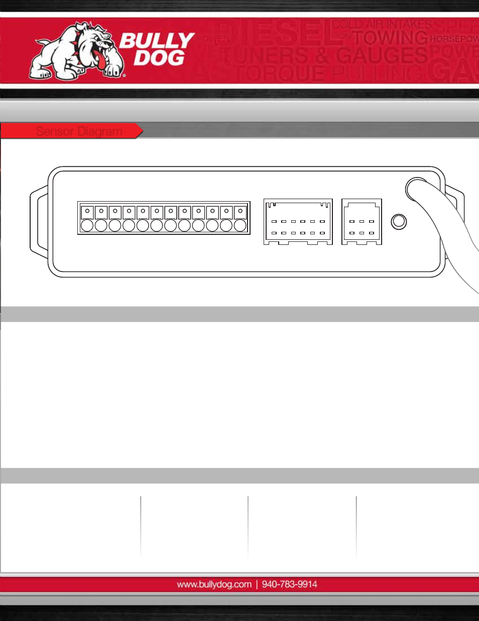
Sensor Docking Station
Part# 40383 | 40384 | 40385
Dock Location Identification Diagram
P1
P2
AN1A
N2
AN3F
-
+
+
+
Y+
PWR
OXYGEN
R- Y+ R-
-
-
+5v
O
U
T
I
N
Sensor Diagram
60