Bird Technologies 61-89A-50 Series-Installation Instructions User Manual
Page 17
Manual 7-9362-2 Page 11
TX RX Systems Inc. 10/19/05
individual plug-in module. These are tri-color LED’s
with green representing NORMAL operation,
orange representing a WARNING condition, and
red indicating a FAULT. A war ning condition
occurs when the current draw of the amplifier
exceeds nominal by +/- 20%. Fault conditions
occur when the current draw exceeds +/- 30% or
the amplifiers operating temperature exceeds 80°
Celsius. The LED for the attenuator card is green
only and indicates DC power applied to the card.
The LED indicators for the power amplifiers are
located on the display panel next to the menu
select buttons and are dual color LED’s. Green
represents NORMAL operation while red indicates
a FAULT condition. Fault conditions occur when
the current draw exceeds 900 ma or falls below
200 ma. Also, whenever the amplifiers operating
temperature exceeds 95° Celsius. The power
amplifiers do not have a warning state.
The power supply LED indicators are located on
display panel next to the menu selection buttons
and are also dual color. Green representing normal
operation and red a fault condition. A fault condi-
tion for the +24 VDC supply occurs whenever the
voltage potential drops below +16 VDC (30%
below nominal). Likewise, a fault for the +12 VDC
supply occurs when the potential is below +8 VDC
(30% below nominal).
FORM-C CONTACTS
Form-C contacts are available inside the cabinet
next to the power supply assembly, see figure 2.
These screw terminals are intended for connection
to the customers supervisory alarm or data acquisi-
tion system. One set of terminals supplies notifica-
tion of any alarm condition occurring and the
second set of contacts indicate the system is oper-
ating on battery backup power.
PERFORMANCE SURVEY
It is a good idea to document the performance of
the system after installation so that a reference
exists for future comparisons. This information can
make troubleshooting an interference problem or
investigation of a complaint about system perfor-
mance much easier. If there are coverage prob-
lems with a system, this survey will usually reveal
them allowing corrective measures to be taken
before the system is put into routine use. The fol-
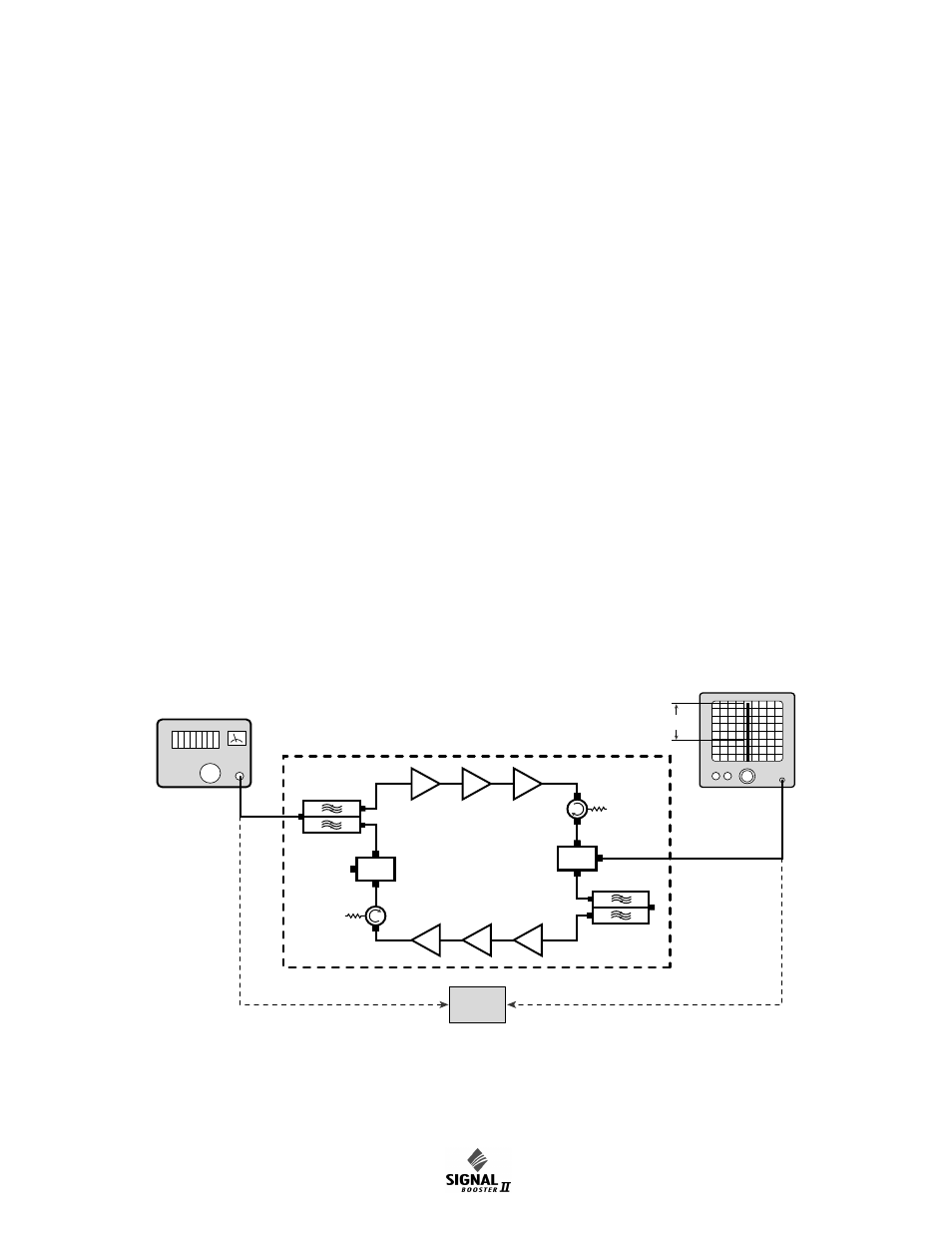
Signal
Generator
Zero
Reference
Spectrum
Analyzer
Gain
Sample
Sample
Test Port
Test Port
Figure 8: Measuring signal booster gain.