Bird Technologies 61-89A-50 Series-Installation Instructions User Manual
Page 10
Manual 7-9362-2 Page 4
TX RX Systems Inc. 10/19/05
It is the customer’s responsibility to make sure
these devices are mounted safely and in compli-
ance with local building codes.
CONNECTIONS
All cabling connections to the booster should be
made and checked for correctness prior to power-
ing up the system.
AC Line
Signal Booster II is designed to be hard-wired to
110 single phase AC lines at 50 - 60 Hz (see
Fig-
ures 2 and 3). An AC line filter is provided for this
purpose. There is a hole provided in the cabinet
bottom-wall for bringing in the AC line. Fasten
quick connect plugs to the incoming AC line, then
connect the ground wire, neutral wire, and hot wire
to the respective pins on the top of the AC line fil-
ter. Refer to the photo shown in Figure 3 below.
The output of the AC line filter is wired into the
switch box which also contains a dual convenience
outlet for running test equipment. Use conduit for
running the wiring into SB II and #14 gauge or
larger conductors.
Backup DC Power
SB II may be run on a DC power source that can
supply 24 to 27 volts DC at 2.5 amps. Screw termi-
nals are provided for this purpose (see figure 2).
This line should be equipped with a fast-acting 3
Amp fuse. Use #16 or #18 gauge wire for this con-
nection.
The power system in SB II automatically switches
to this backup DC input when the AC supply fails
for any reason including a power outage or inten-
tional disconnection.
It is not necessary that this connection be made for
normal operation on the AC line.
Alarm Terminals (Form-C contacts)
Two sets of contacts are provided to monitor the
general operating condition of SB II and are
intended for connection to a supervisory system.
See figure 2.
One set changes state when the AC power supply
shuts down for any reason and the unit switches to
operation on the backup DC power system.
The other set of contacts changes state when any
of a number of fault conditions arises within the
electronics such as current drain outside of the
expected operating range in some module.
A six-terminal strip is provided for the interface and
uses screw terminals for ease of connection. Route
the alarm wires through one of the access holes in
the bottom of the box, strip about 3/16” of insula-
tion from each end, loosen the screw terminal,
insert and retighten. Use #20 or #22 gauge insu-
lated wire.
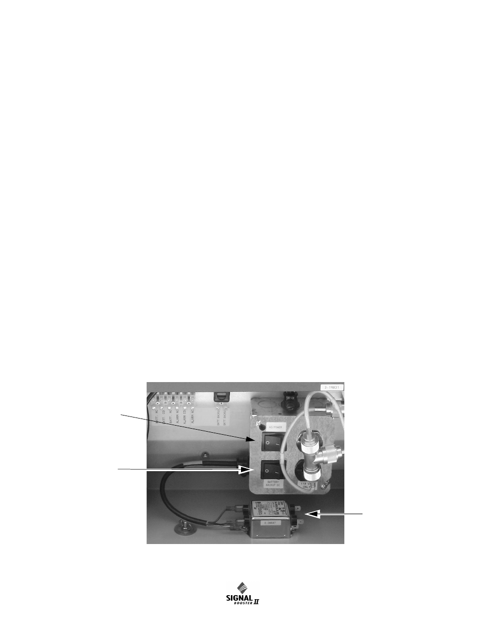
Figure 3: Wiring of AC line entry.
Connect
incoming AC
here
AC Power
Switch
Battery
Backup
Switch