Chapter 4 operating instructions, Normal operation, Figure 7 element direction – Bird Technologies APM-16 User Manual
Page 25
13
Chapter 4
Operating Instructions
Normal Operation
1.
Insert the element in the line section socket.
2.
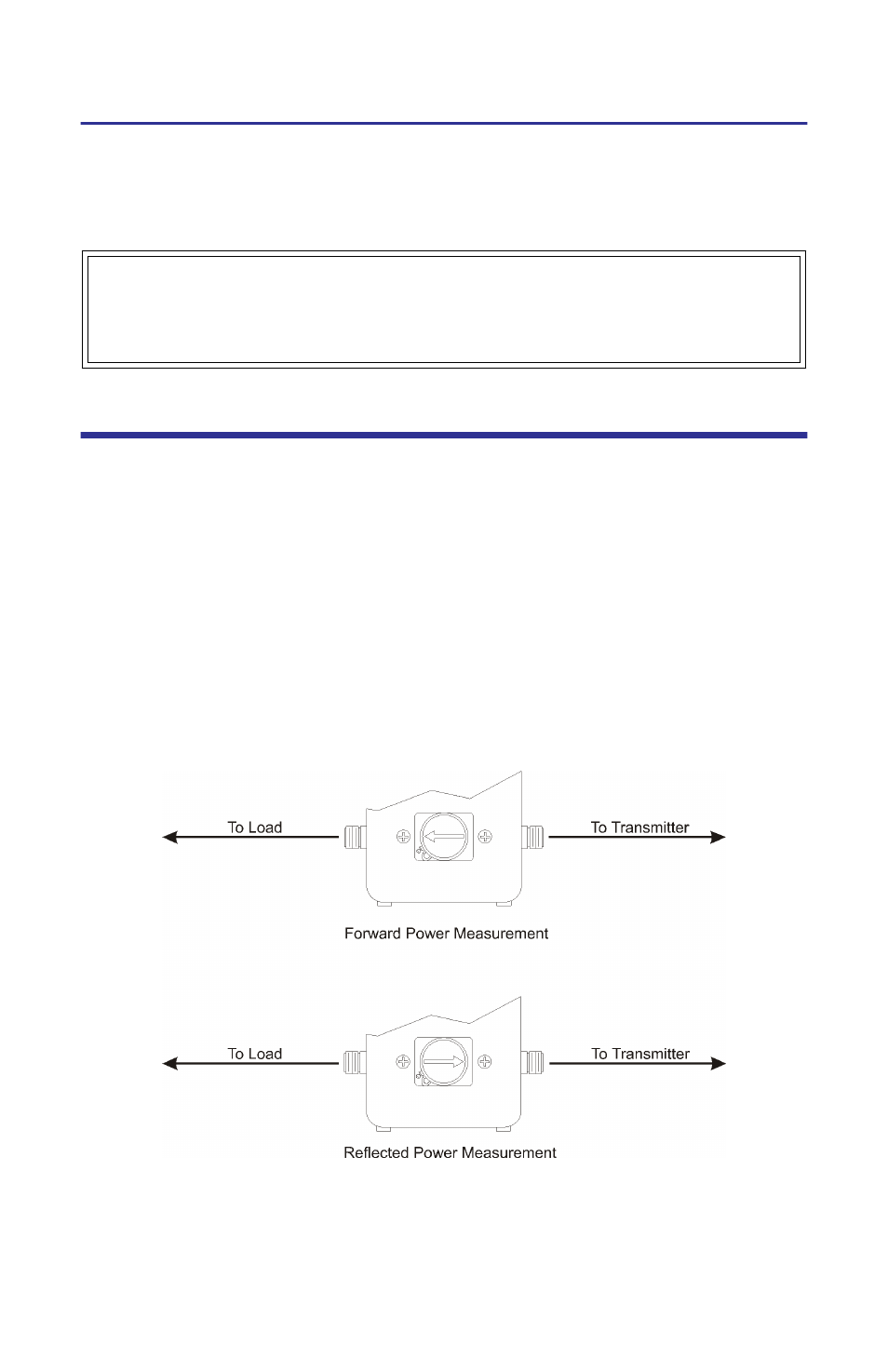
To measure forward power, turn the element so that the arrow points
towards the load.
3.
To measure reflected power, turn the element so that the arrow points
towards the source.
4.
Turn on the RF source.
5.
Read the power using the scale whose full-scale marking matches the ele-
ment’s maximum power.
Figure 7 Element Direction
For your convenience, a pair of VSWR conversion graphs are included in this
manual. With these charts, VSWR can be determined from the forward and
reflected power. Find the intersection of the forward and reflected power mea-
surements. The slanted line passing closest to this point is the VSWR.
WARNING
RF voltage may be present in element socket. Keep element in socket during
operation.
- SK-4000-TC-Manual (56 pages)
- SK-4000-TC-Datasheet (2 pages)
- SH-36S-Manual (206 pages)
- SH-36S-Datasheet (4 pages)
- SH-36S-PC-Manual (130 pages)
- SH-36S-PC-Datasheet (2 pages)
- SH-36S-PC-Quick Start (2 pages)
- SH-36S-RM-Datasheet (2 pages)
- SA-3600XT-Manual (112 pages)
- SA-3600XT-Datasheet (2 pages)
- AT-500-Manual (73 pages)
- AT-500-Datasheet (2 pages)
- AT-800-Manual (74 pages)
- 89-83F-02-03-Manual (2 pages)
- 89-83F-02-03-Datasheet (1 page)
- 8251 Series-Datasheet (1 page)
- 8251 Series-Manual (30 pages)
- DA10 VHF Series-Datasheet (2 pages)
- DA10 VHF Series-Manual (47 pages)
- 8865SC13-Datasheet (2 pages)
- 8865SC13-Manual (28 pages)
- 8890-300SC13-Manual (28 pages)
- 8921SC13-Manual (28 pages)
- 8931-115SC13-Manual (34 pages)
- BDS-Datasheet (2 pages)
- BDS-Manual (98 pages)
- SCC7 Series-Datasheet (2 pages)
- SCC7 Series-Manual (45 pages)
- MSCC7 Series-Datasheet (2 pages)
- MSCC7 Series-Manual (35 pages)
- SCC8 Series-Datasheet (2 pages)
- SCC8 Series-Manual (47 pages)
- 4020 Series-Datasheet (1 page)
- 4020 Series-Manual (4 pages)
- 4027A Series-Datasheet (2 pages)
- 4027A Series-Manual (6 pages)
- 4027F Series-Datasheet (2 pages)
- 4027F Series-Manual (6 pages)
- 4028 Series-Datasheet (2 pages)
- 4028 Series-Manual (6 pages)
- 7022-Datasheet (4 pages)
- 7022-Manual (27 pages)
- ACM Series-Datasheet (2 pages)
- ACM Series-Manual (40 pages)
- BPME Series-Datasheet (4 pages)