Bird Technologies 28-69-04A User Manual
Page 12
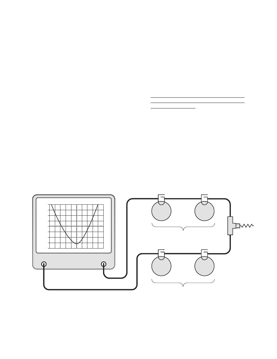
14. Terminate the antenna connector with a 50
ohm load. Connect the output of the tracking
generator to the equipment port of one of the
duplexer channels and the spectrum analyzer
input to the equipment port of the remaining
channel as shown in figure 7.
15. Set-up the analyzer / generator to sweep
across the rejection notch frequency of the
channel being tuned. The center of the display
should be set to the desired center frequency
of the rejection notch being adjusted. Set the
vertical scale of the analyzer / generator to 10
dB/div.
Keep in mind that the high frequency channel
has it's rejection notch set to reject the low fre-
quency signal and vice-versa for the rejection
notch of the low frequency channel.
16. Insure that the IFR A-7550 menu's are set as
follows:
DISPLAY - line
MODE - live
FILTER - none
SETUP - 50 ohm/dBm/gen1
17. Set the analyzers attenuation control so that
the 0 dBm level is at the top of the display.
The display will now show most of the rejec-
tion notch. Using the analyzer's attenuation
control adjust the amount of attenuation so
that the "peak" or lowest value on the rejection
notch is displayed.
18. The cavities rejection notches are adjusted
(for maximum rejection) by gently turning the
variable capacitors in the loop plate assem-
blies. Move between filters as needed.
Because of the filters sensitivity to tool con-
tact, an insulated tuning tool must be used to
make the adjustment..
19. Adjust the rejection notch of the remaining
cavities by changing the sweep frequency of
the analyzer / generator to match the new re-
jection notch frequency. The equipment stays
connected as it is.
20. Repeat step 17 and 18 for the remaining
channel (cables and equipment stay con-
nected where they are).
21. With the tuning completed, reconnect the
equipment cables and antenna feedline. Test
the system for proper operation.
TX RX Systems Inc. Manual 7-9177-1 09/19/97 Page 8
GENERATE
OUTPUT
ANALYZER
INPUT
dBm
-30
-40
-50
-60
-70
-80
-90
-100
-110
30
0
10
300
dBm
dB ATT
GEN
dBM
MSEC
KHz RES
KHz/DIV
50
MHz
50
Ω
Load
Vari-
Notch
Filter
Vari-
Notch
Filter
Vari-
Notch
Filter
Vari-
Notch
Filter
High Frequency Pass Channel
Reject the Low Frequency Channel
Low Frequency Pass Channel
Reject the High Frequency Channel
Figure 7: Equipment setup for fine tuning the rejection notch of each channel.