Rejection notch – Bird Technologies 28-69-04A User Manual
Page 11
4. Set-up the analyzer / generator to the desired
frequency (center of display) and for a vertical
scale of 10 dB/div.
5. Do not connect the RLB to the duplexer at this
time, leave the "load" port on the bridge open.
This will supply the maximum amount of re-
flected energy to the analyzer input.
6. Insure that the IFR A-7550 menu's are set as
follows:
DISPLAY - line
MODE - live
FILTER - none
SETUP - 50 ohm/dBm/gen1.
7. The flat line across the screen is the return loss
curve. Select the "MODE" main menu item and
then choose the "STORE " command.
8. Next select the "DISPLAY" main menu item
and choose the "REFERENCE" command.
This will cause the stored value to be displayed
at the center of the screen as the 0 dB refer-
ence value.
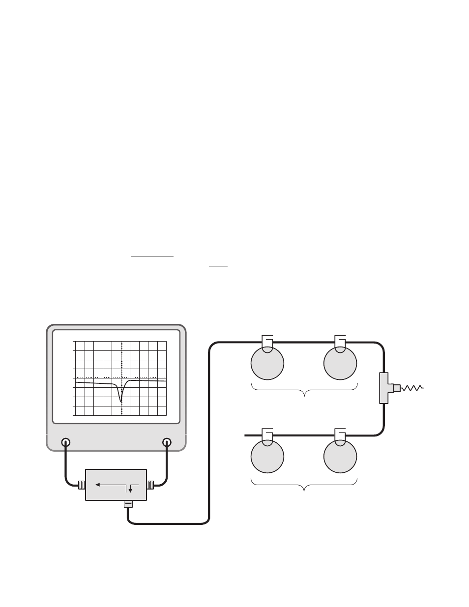
9. Connect the "load" port on the RLB to the
equipment port of the channel to be fine tuned.
Terminate the duplexers antenna connector
with the 50 ohm load. The equipment port of
the remaining duplexer channel is left discon-
nected, refer to figure 6.
10. The display will now present the combined re-
turn loss curve for all of the cavities in the
channel. The channels passband is that fre-
quency range over which the return loss is 15
dB or greater.
11. Fine tune the passband for the entire channel
(for maximum return loss) by gently adjusting
the positions of the fine tuning rods (coarse
rods if needed) moving between cavities as
required. Once the desired response is ob-
tained "lock" the tuning rods into place by
tightening the 1/4" shaft lock nuts and the
knurled thumb nuts on each filter.
12. Move the cable from the RLB's "load" port to
the equipment port of the other channel. This
will allow the remaining duplexer channel to be
fine tuned. Reset the analyzer / generator cen-
ter frequency. Repeat steps 10 and 11.
13. The
rejection notch
for each of the channels
must be fine tuned next.
TX RX Systems Inc. Manual 7-9177-1 09/19/97 Page 7
GENERATE
OUTPUT
ANALYZER
INPUT
dBm
40
30
20
10
0
-10
-20
-40
-40
40
0
10
300
dBm
dB ATT
GEN
dBM
MSEC
KHz RES
KHz/DIV
500
MHz
Load
So
ur
c
e
R
e
fl
e
c
ted
50
Ω
Load
Vari-
Notch
Filter
Vari-
Notch
Filter
Vari-
Notch
Filter
Vari-
Notch
Filter
High Frequency Pass Channel
Reject the Low Frequency Channel
Low Frequency Pass Channel
Reject the High Frequency Channel
RLB - 150 BRIDGE
(RLB)
Figure 6: Equipment setup for fine tuning the passband of each channel.