Bird Technologies 8255 User Manual
Page 26
These tests are by no means a necessity to the operation
of the load but merely guidelines for the users informa-
tion and advisement.
Disassembly
There are no special techniques required for the repair or
replacement of components in these Termaline Load Re-
sistors.
Tools
Required
Models 8251 and 8255 - A screwdriver and a small
wrench are they only tools needed for these models.
Model 8252 - A screwdriver, a small wrench, and an ad-
justable wrench (for the connector bolts) will be needed.
RF Connector
This section applies to the Models 8251 and 8255. (The
Model 8252 has a 3-1/8 inch EIA flanged connector and
must be returned to the factory for connector replace-
ment). The connector on the Models 8251 and 8255 are
“Quick-Change” design that permits easy interchange
with the use of only a screwdriver. This process does not
interfere with the essential coaxial continuity of the load
resistor RF input or the coolant oil seal. For replacement,
proceed as follows:
1. Remove the four 8-32 x 5/16 screws from the cor-
ners of the RF connector flanges.
2. Pull the connector straight out of its socket.
Bird Model 8251/52/55 Termaline Coaxial Load Resistor
14
50.0
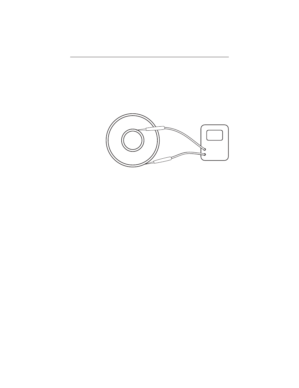
Figure 3
Measuring DC
Resistance