Dc resistance, Figure 6 measuring resistance – Bird Technologies 8931-230SC13-Manual User Manual
Page 24
Bird 8930 Series Semiconductor Termaline Coaxial Load Resistor
14
DC Resistance
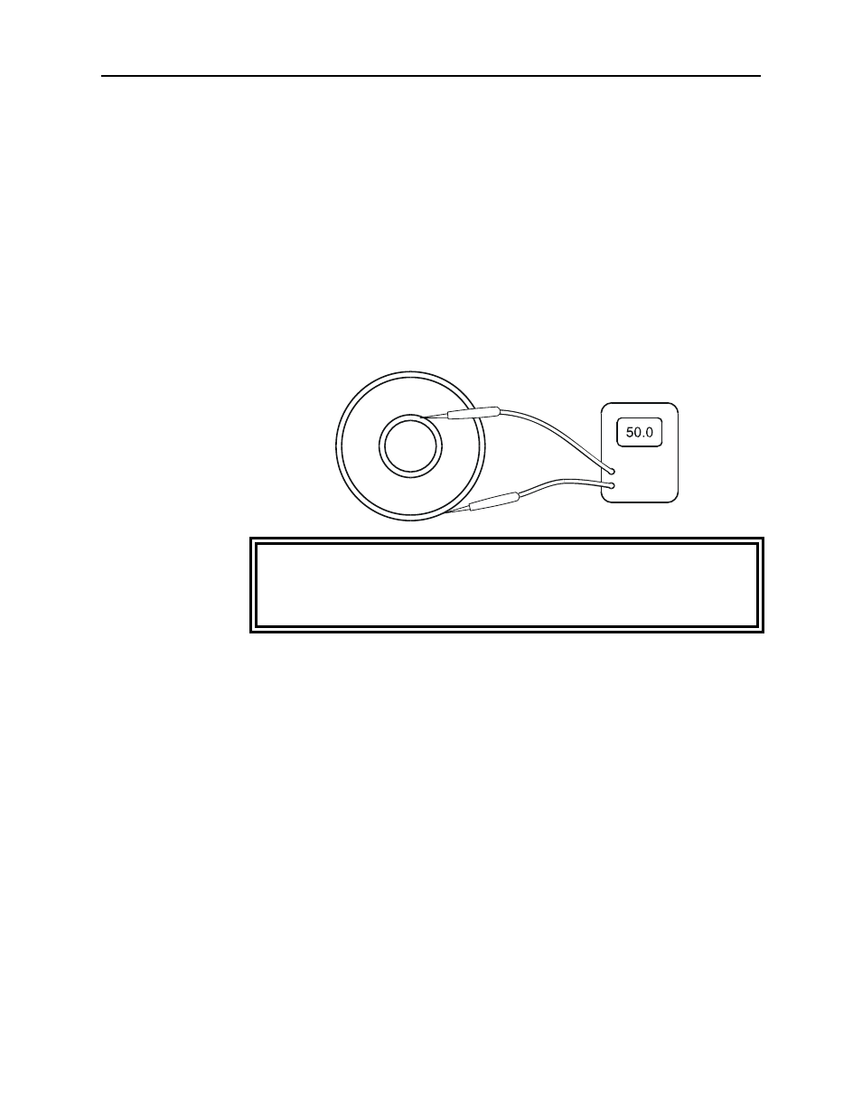
Measuring the dc resistance between the inner and outer conductors
of the RF connector shows changes in the load over time, a good check
of the load resistor’s condition. Under normal operating conditions,
the resistor should provide at least 5,000 hours of operation before
requiring any additional service. DC resistance tracking must start
before the load is put into service, and should be measured annually.
Perform the following steps and record the value for future
comparison. Make sure that you have an ohmmeter with an accuracy
of ±1% at 50 ohms and that the load temperature is between 20 and
25 °C (68 to 77 °F) before starting.
y
Turn off the RF power and interlock circuitry.
y
Disconnect the RF line.
y
Connect the multimeter test leads to the center and outer
conductor of the load resistor. Refer to Figure 6.
y
Compare the measured value with the previous measurement and
with the baseline resistance, measured when the load was put
into service. If the new value differs from either of these by more
than 1 ohm this could indicate a failing resistor.
Figure 6
Measuring
Resistance
WARNING
Never attempt to connect or disconnect RF equipment from the
transmission line while RF power is being applied.
Leaking RF energy is a potential health hazard.