Ad-is everflow, Air dryer operation, Normal brake cycle – Bendix Commercial Vehicle Systems AD-IS EVERFLOW User Manual
Page 4
4
AD-IS EVERFLOW
AIR DRYER OPERATION:
GENERAL
The Bendix
®
AD-IS
®
EverFlow
®
assembly alternates
between the dryers each time the brake system charges.
During high air demand, the dryers alternate every 30
seconds to allow drying of the added volume of air. A
pressure protection valve is needed after the dryers to
maintain at least 70 PSIG at the dryers during high air
demand. A Bendix
®
EverFlow
®
electronic module monitors
the air brake system and determines the amount of
demand. The AD-IS EverFlow assembly requires a
signal from the delivery port of the governor into the
GOV port of the EverFlow
electronic module. The AD-IS
EverFlow assembly also needs a supply air line from the
secondary tank to the electronic module RES port.
This
line must be 3/8 inch, or larger, tubing.
The AD-IS EverFlow assembly is primarily designed to dry
air on systems used for bulk unload and central tire inflation.
The system operates best when a pressure protection valve
is installed between the EverFlow assembly and the source
of the high volume air. Refer to the system schematics,
Figure 2. This pressure protection valve should have a
minimum pressure of 70 PSIG.
Delivery pressure in
excess of 175 PSIG can cause the purge valve to cycle
rapidly between load and purge mode.
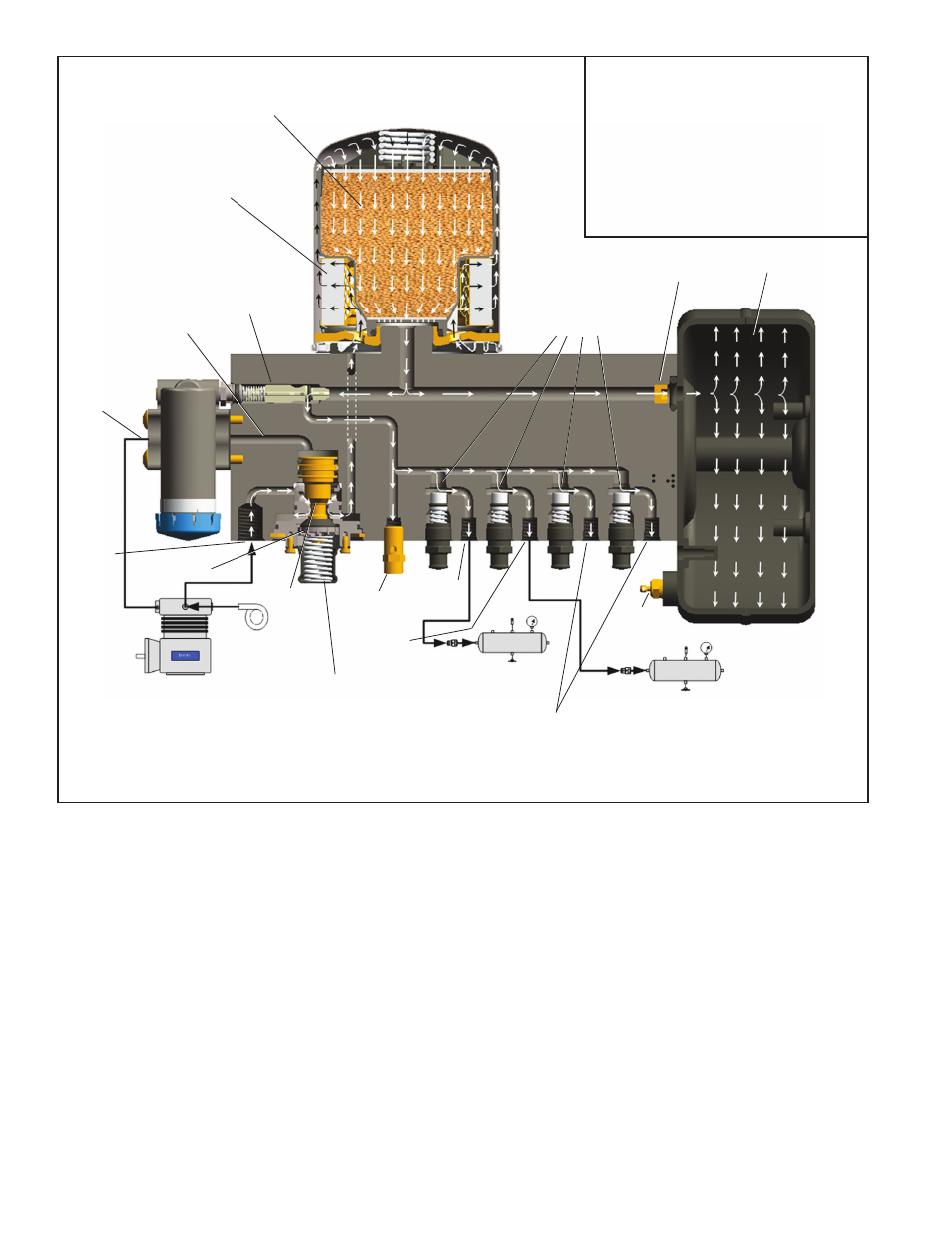
NORMAL BRAKE CYCLE
(Refer to Figures 3 & 4)
When the compressor is charging (compressing air) air
flows through the compressor discharge line to the inlet
(1 IN) port of one of the air dryers. The compressed air
includes contaminates such as oil, oil vapor, water and
water vapor. The air then flows into the desiccant cartridge,
where it flows through a liquid separator which collects
liquids and other contaminants.
COMPRESSOR
GOVERNOR
DESICCANT
BED
DELIVERY
CHECK VALVE
(OPEN)
PRIMARY
PORT (PRI)
PURGE VALVE
(CLOSED)
TURBO
CUT-OFF
VALVE
(OPEN)
ENGINE
TURBO
UNLOADER
PORT
SUPPLY
PORT
PRIMARY
RESERVOIR
PRESSURE
PROTECTION
VALVES
AUXILIARY PORTS
(TO ACCESSORIES)
SEE
NOTE 1
Note 1:
The Bendix
®
AD-IS
®
air dryer and reservoir
system purge piston has a purge control
channel drain. This allows any condensation
in this area to flow past a diaphragm in the
top of the purge piston and out through a
channel in the middle of the central bolt of
the purge assembly to be drained. During
the purge cycle this drain is closed.
SAFETY
VALVE
PURGE
RESERVOIR
DRAIN VALVE
SECONDARY
RESERVOIR
SECONDARY
PORT (SEC)
PURGE
RESERVOIR
PURGE
ORIFICE
OIL COALESCING FILTER
(BENDIX
®
AD-IS
®
PURAGUARD
®
OIL COALESCING AIR DRYER)
A
D
C
B
PURGE
CONTROL
CHANNEL
FIGURE 3 -
BENDIX
®
AD-IS
®
AIR DRYER AND RESERVOIR SYSTEM CHARGE CYCLE