Bendix Commercial Vehicle Systems VERSAJUST AUTOMATIC SLACK ADJUSTER User Manual
Page 5
5
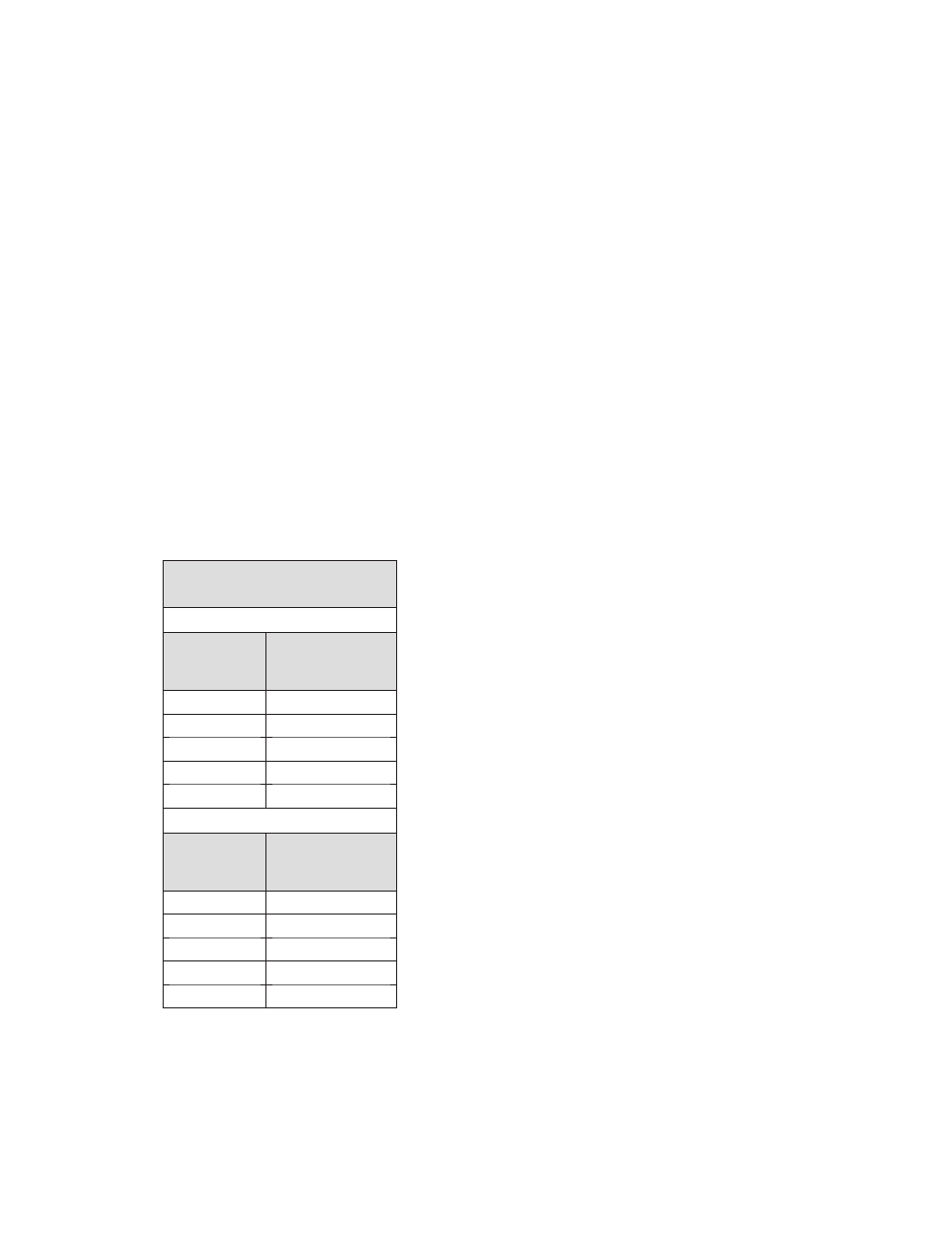
3. Measure the brake actuator push rod stroke while
making an 80-90 psi service brake application. Actuator
push rod strokes should not exceed the values shown in
Chart 2, on this page. The correct pressure for this test
can be achieved as follows: Build the system pressure
up to a 100 psi reading on the vehicle gauge. Shut the
engine off. Fan the brakes to attain a 90-95 psi reading.
Make and hold a full brake application while the strokes
are checked.
IF THE SLACK ADJUSTER DOES NOT
AUTOMATICALLY ADJUST THE BRAKES
If the actuator stroke exceeds those shown in the
stroke table, inspection of the foundation brake and/or
the automatic slack is necessary. Maintenance of the
foundation brake may be a factor in the excessive stroke
conditions. Inspecting the foundation brake – per the
Brake Maintenance Inspection presented in this manual –
should determine how much of the long stroke condition
is caused by the condition of the foundation brake. The
Bendix Versajust slack adjuster can be tested using the
instructions presented in this manual under "Testing
the Bendix
®
Versajust
™
Adjuster Mechanism." The
automatic slack adjuster is not designed to function as a
manual adjuster once it is unable to maintain adjustment
automatically. Manual adjustment should be done only as
a temporary measure to correct brake adjustment in an
emergency situation. The routine manual adjustment of
an automatic slack adjuster that is still within adjustment
limits may shorten its service life. Automatic slack adjusters
should not be manually adjusted in an effort to correct
excessive push rod stroke. This condition indicates that
a problem exists with the automatic adjuster; with the
installation of the adjuster; or with related foundation
brake components, which manual adjustment will not
fix. Replacement of the automatic slack adjuster or other
foundation brake components may be necessary. Consult
with the manufacturer's troubleshooting guidelines to find
and fix the problem.
WARNING:
Manual adjustment of automatic slack
adjusters is a dangerous practice that could have
serious consequences. This is because it can give
the operator a false sense of security about the
effectiveness of the brakes, which are likely to go
out of adjustment again soon. Do not make manual
adjustments of an automatic slack adjuster once it
can no longer automatically adjust the brakes. Manual
adjustment DOES NOT fix the underlying wheel end
adjustment problem. As soon as possible, have the
vehicle inspected by a qualified technician or consult
the manufacturer's troubleshooting guidelines to find
and fix the problem.
2. Lubricate the automatic slack adjuster through the lube
fitting with a quality multipurpose chassis lubricant
(N.L.G.I. Grade 2).
Lubricate the slack adjuster until clean lubricant flows
from the grease relief opening in the boot.
3. Perform the In Service Inspection described in this
manual.
IN SERVICE INSPECTION
1. Apply and release the vehicle brakes several times
while observing the Bendix
®
Versajust
™
slack adjuster.
The Versajust slack adjuster and brake actuator should
move freely, without binding or interference, and
should return to the full released position. Observe
the looseness that exists between the yoke and
adapter bushing and the yoke and link pins and their
mating parts (yoke, body, link). Replace these parts if
looseness appears excessive. Make certain the brake
actuator push rod jam nut is tight against the yoke
adapter.
2. Inspect the Versajust slack adjuster for physical
damage, paying particular attention to the link, boot,
and yoke. Inspect for bent, broken, loose, or misaligned
brake actuator push rods and cracked or damaged
brake actuator brackets. Repair or replace any
components found to be damaged.
ACTUATOR
STROKE TABLE
STANDARD STROKE
Brake Actuator
Size
Recommended
Maximum
Operating Stroke
30
2"
24
1
3
/
4
"
20
1
3
/
4
"
16
1
3
/
4
"
12
1
3
/
8
"
LONG STROKE
Brake Actuator
Size
Recommended
Maximum
Operating Stroke
30LS
2
1
/
2
"
24L
2"
24LS
2
1
/
2
"
20L
2"
16L
2"
CHART 2 - ACTUATOR STROKE TABLE