0 operation – Bendix Commercial Vehicle Systems BlindSpotter SD User Manual
Page 4
4
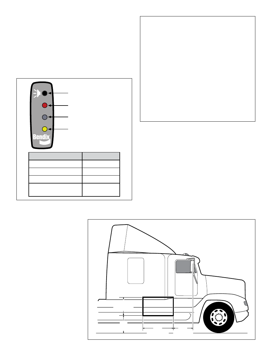
22"
(558.8mm)
18"
(457.2mm)
48"
(1219.2mm)
14"
(355.6mm)
•
an audible warning: When the vehicle’s turn signal
is active and the sensor detects a large metallic object
alongside the vehicle, the side sensor display emits
an audible warning tone.
•
Volume Control: Steps the volume level of the alerts
between low, medium and high (and back through the
sequence). The most recent selection is stored in the
memory.
•
an ambient light Detector: Automatically adjusts
the brightness of the LEDs.
If the system detects a failure and becomes inoperative, the
display unit will warn the driver by continuously illuminating
both the red and yellow LEDs at the same time.
1.0 OPERaTION
OPERaTOR DISPlay UNIT
See Figure 3
.
The Bendix
™
BlindSpotter
®
Radar system assists the driver
by giving audible and visual alerts.
•
a visual warning: The side object display unit uses
two (2) LED indicators to display the status of the side
radar sensor. The yellow LED indicates the system
is active, but no objects are detected. The red LED
indicates the system is detecting an object.
LED
Indication
Red Indicator
Object Detected
Yellow Indicator
No Object Detected
Red and Yellow (at power-up) Self-Test
Red and Yellow (constant)
Sensor Diagnostic
Trouble Code (DTC)
Volume Control Button
Red LED: Alert
Ambient Light Sensor
(Automatically Dims LEDs)
Yellow LED: Standby;
No Object Detected
FIGURE 3 - Bendix
BlindSpotter driver diSplay Unit
led indicatorS
Operation Section Index
1.0 Operation . . . . . . . . . . . . . . . . . . . . . 4
1.1 Range . . . . . . . . . . . . . . . . . . . . . . . 5
1.2
Sensor Location . . . . . . . . . . . . . . . . . . 5
1.3
Sensor Orientation. . . . . . . . . . . . . . . . . 5
1.4
Operator Display Unit Mounting . . . . . . . . . . 4
1.5
What To Expect When Using The
Bendix BlindSpotter System . . . . . . . . . . . . 6
1.6
Alerts And Warnings . . . . . . . . . . . . . . . . 7
1.7
Bendix BlindSpotter System Diagnostic
Trouble Codes . . . . . . . . . . . . . . . . . . . 7
1.8
Radar Sensor Replacement . . . . . . . . . . . . 6
1.9
Alert Volume . . . . . . . . . . . . . . . . . . . . 6
1.10 Potential False Alerts . . . . . . . . . . . . . . . 6
1.11 Radar Clearance . . . . . . . . . . . . . . . . . 6
FIGURE 4 - recommended
inStallation location
(Single SenSor SyStemS)