Bendix Commercial Vehicle Systems BlindSpotter SD User Manual
Page 11
11
3.3 ElECTRICal SUPPly TROUBlEShOOTING PRE-TESTS
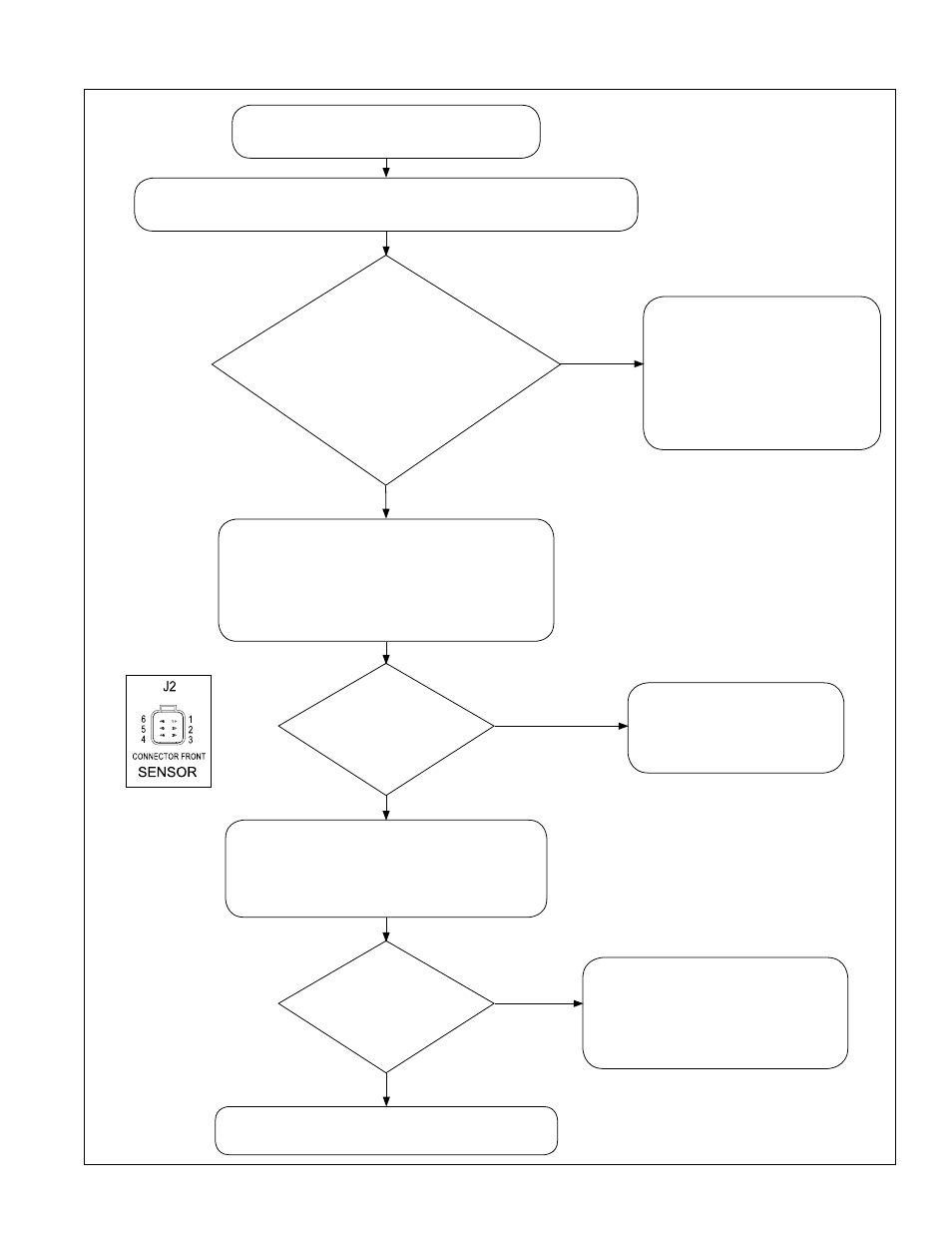
Use the vehicle
manufacturer’s recommended
procedures to make repairs
as needed.
Re-run the power-up test.
(See Table 1)
Repair the ground path
to the system.
Re-run the power-up test.
Repair the power path to the
system. The fuse may be blown.
Reconnect all connectors.
Re-run the power-up test.
Is
the
supplied
voltage in the permitted
range?
(12 volt systems: range is 11-13 volts.
For 24 volt systems:
the range is 22-26
volts.)
Is
the
resistance in
the range 0 to
0.5 Ohms?
Is
the
voltage within
0.5 volts of battery
voltage?
YES
YES
NO, the voltage
is out-of-range
NO, the voltage
is out-of-range
Ignition Power ON, but no LEDs
illuminate.
Consult the vehicle manufacturer’s service manual and use the
recommended procedures to check the battery and charging system.
Power OFF. Disconnect the negative (-)
battery cable.
Disconnect the harness at the sensor (J2).
Measure the resistance between Pin 2 of the
harness connector J2, and chassis ground.
Power OFF. Connect the negative (-)
battery cable. Power ON.
Measure the voltage between Pin 1 of the
harness connector J2, and chassis ground.
Pre-tests completed, go to Section 3.3.
YES
NO, the resistance
is out-of-range
Harness