Bendix Commercial Vehicle Systems BlindSpotter SD User Manual
Page 14
14
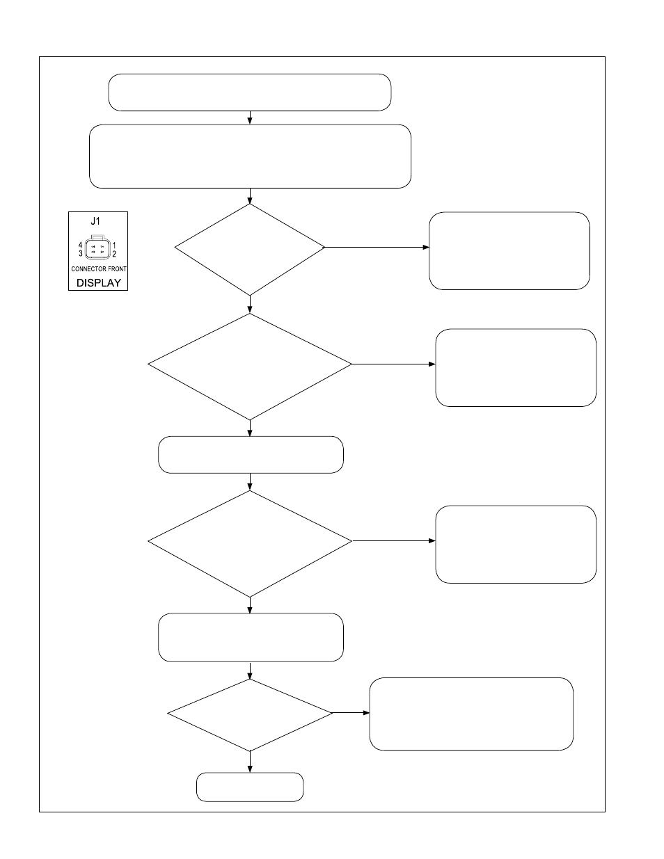
3.6 TROUBlEShOOTING WhEN ThE alERT TONE IS NOT FUNCTIONING
Repair the wiring harness.
Re-test the detection zone
(Section 3.7)
Re-run the power-up test.
Repair the wiring harness.
Re-test the detection zone
(Section 3.7)
Re-run the power-up test.
Repair the wiring harness.
Re-test the detection zone
(Section 3.7)
Re-run the power-up test.
Repeat this test to double-check
the results of the test. If a second
test does not find any abnormalities,
replace the Operator Display Unit.
Is
the
resistance in
the range 0 to
0.3 Ohms?
Is
the
resistance between
Pins 2 and 4 of the J1 harness
connector in the range 0
to 0.5 Ohms?
Is
the
voltage between
Pins 2 and 4 of the J1 harness
connector, in the range
10 to 14 volts?
Is
the alert
tone now functioning?
YES
YES
YES
NO, the resistance
is out-of-range
NO, the voltage
is out-of-range
NO, the resistance
is out-of-range
NO
Troubleshooting Section 3.3 indicates that the alert
tone is not functioning (Red LED only during alerts)
Power ON. Activate turn signal
(for the side being inspected.)
Power OFF. Re-connect all
connectors. Re-test the detection
zone (Section 3.7)
Test Complete
YES
Power OFF.
Disconnect the harness at the Operator Display Unit (J1).
Measure the voltage between Pin 4 of the harness connector J1,
and the turn signal source (for the side being inspected).