Bendix Commercial Vehicle Systems AD-9 IPC AIR DRYERS 4/11 User Manual
Page 3
3
CHECK
VALVE
ORIFICE
PURGE
VOLUME
DELIVERY
PORT
HEATER
ELEMENT
SUMP
EXHAUST
PURGE
VALVE
RESERVOIR
SUPPLY
PORT
COMPRESSOR
GOVERNOR
ENGINE
TURBO
CONTROL
PORT
OIL
SEPARATOR
DESICCANT
BED
DESICCANT
CARTRIDGE
TURBO
CUT-OFF
PISTON
CHECK
VALVE
ASSEMBLY
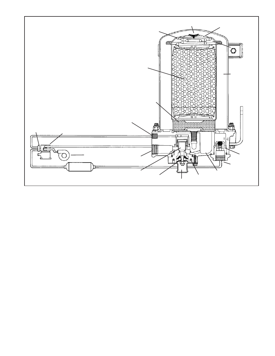
FIGURE 3 - BENDIX
®
AD-9
®
AND AD-9
®
IPC AIR DRYER PURGE CYCLE
changes several times, reducing the temperature, causing
contaminants to condense and drop to the bottom, or sump,
of the air dryer end cover.
After exiting the end cover, the air fl ows into the desiccant
cartridge. Once in the desiccant cartridge, air fi rst fl ows
through an oil separator which removes water in liquid form
as well as oil and solid contaminants.
Air exits the oil separator and enters the desiccant drying
bed. Air fl owing through the column of desiccant becomes
progressively drier as water vapor adheres to the desiccant
material in a process known as “adsorption”. The desiccant
cartridge using the adsorption process typically removes
95% of the water vapor from the pressurized air.
The majority of dry air exits the desiccant cartridge through
its integral single check valve to fi ll the purge volume
between the desiccant cartridge and outer shell. Some
air will also exit the desiccant cartridge through the purge
orifi ce adjacent to the check valve.
Dry air fl ows out of the purge volume through the single
check valve assembly and out the delivery port to the fi rst
(supply) reservoir of the air system.
The air dryer will remain in the charge cycle until air brake
system pressure builds to the governor cut-out setting.
PURGE CYCLE (Refer to Figure 3)
When air brake system pressure reaches the cut-out setting
of the governor, the compressor unloads (air compression
stopped), and the purge cycle of the air dryer begins. When
the governor unloads the compressor, it pressurizes the
compressor unloader mechanism and line connecting the
governor unloader port to the air dryer end cover control
port. The purge piston moves in response to air pressure,
causing the purge valve to open to atmosphere and
(partially) closing off the supply of air from the compressor.
(This will be further discussed in the section covering
the turbo cut-off feature.) Contaminants in the end cover
sump are expelled immediately when the purge valve
opens. Also, air – which was fl owing through the desiccant
cartridge – changes direction and begins to fl ow toward
the open purge valve. Oil and solid contaminants collected
by the oil separator are removed by air fl owing from the
desiccant drying bed to the open purge valve.