Cleaning & inspection – Bendix Commercial Vehicle Systems AD-9 IPC AIR DRYERS 4/11 User Manual
Page 13
13
Heater and Thermostat Assembly Removal
1. Remove the two screws that secure the heater and
thermostat assembly to the purge valve assembly. See
Figure 9, illustration L for kit contents.
CAUTION
DO NOT PULL THE HEATER & THERMOSTAT
ASSEMBLY STRAIGHT OUT OF THE PURGE VALVE
BODY! READ STEP 2 COMPLETELY BEFORE
ATTEMPTING REMOVAL.
2. Study Figure 10 closely and note the "Y" shape of the
Heater & Thermostat assembly in its installed position
in the purge valve housing. As illustrated, remove the
heater & thermostat assembly by gently "rotating" the
connector to the left (Step A) until the thermostat clears
the purge valve housing, then slide the heater element
out, to the right and up (Step B).
End Cover Removal
1. Remove the remaining six 3/8" cap screws, locknuts
and twelve special washers that secure the end cover to
the housing air dryer housing. Separate the end cover
and desiccant cartridge from the housing. See Figure
9, illustration K.
2. Remove the end cover to outer housing o-ring.
3. Do not remove the safety valve from the end cover
unless it has been proven defective. If replacement
is required, apply thread sealant or Teflon
®
tape on
the threads of the replacement valve and torque
to 120–400 in. lbs. See Figure 1 for safety valve
location.
4. Place a strap or chain wrench around the desiccant
cartridge so that it is approximately 2–3 inches
away from the end cover. Rotate the cartridge
counterclockwise until it completely separates from the
end cover.
Note: A substantial torque (up to 50 lb. ft.) may be
required to perform this disassembly.
5. Remove the desiccant cartridge o-ring from the end
cover.
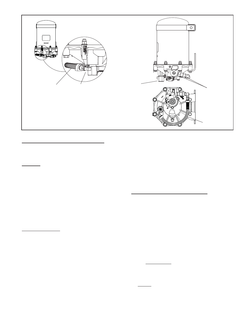
Drop In Air Dryer Makeup Line Removal
1. Before beginning, note the approximate angle of
the fittings, check valve and the general routing of
the makeup line on the air dryer. It is important that
the same approximate routing be duplicated during
re-installation. See Figure 11.
2. Disconnect the makeup line from the 90 degree fi tting
on the check valve.
3. Disconnect the makeup line from the 90 degree fi tting
on the port adapter itself or the check valve. Remove
the adapter along with the attached 90 degree fi tting.
CLEANING & INSPECTION
1. Using mineral spirits or an equivalent solvent, clean
and thoroughly dry all metal parts.
2. Inspect the interior and exterior of all metal parts
that will be reused for severe corrosion, pitting and
cracks. Superficial corrosion and/or pitting on the
exterior portion of the upper and lower body halves is
acceptable.
3. Inspect the bores of both the end cover and the purge
valve housing for deep scuffi ng or gouges.
DELIVERY PORT
ADAPTER
(WITH 90° FITTING)
DELIVERY PORT
ADAPTER
(WITH 90° FITTING)
MAKEUP AIR LINE
CHECK VALVE
(WITH 90° FITTING)
SPECIAL ASSEMBL
Y,
MUST BE REPLA
CED B
Y
AD
-9 SOFT SEA
T
AIR DR
YER ASSY
.
SPECIAL ASSEMBL
Y,
MUST BE REPLA
CED B
Y
AD
-9 SOFT SEA
T
AIR DR
YER ASSY
.
FIGURE 11 - BENDIX
®
AD-9
®
DROP IN AIR DRYER
MAKEUP AIR LINE