0 assembly – Baumfolder Flexifold: 2st Station (from 2005) User Manual
Page 22
TP10495A
PAGE 22
Figure 4.1-1
WARNING
Do not plug the power cord into an AC outlet
until the Flexifold 2nd Station is fully as-
sembled, adjusted and ready to use. Unplug the
Easyfold any time disassembly is required.
4.0 ASSEMBLY
4.1 Main Unit
To assemble the Flexifold 2nd Station unit, first
remove the four bolts holding it to the skid. Place the folder
on the stand (See Figure 4.1-1).
4.3 Delivery Table
WARNING
Do not run machine without delivery table
installed in machine.
To install the delivery table, insert the
delivery table with the drive wheel toward the fold rolls.
Slide the delivery table over both sets
of locating pins.
The first notch in the front part of the
delivery table should rest on the pins. Then drop the rear
notch down on the rear dowel pins.
Rotate the handwheel to check that the gears are properly
meshed.
Plug the delivery table into the table receptacle on
the input/output power assembly.
4.4 Cross Carrier Assembly Installation
WARNING
Do not run machine without cross carrier and all
guards in place.
Insert the Cross Carrier with the gears toward the
fold rolls. Slide the Cross Carrier table over both sets of
locating pins.
The first notch in the front part of theCross Carrier
should rest on the pins. Then drop the rear notch down on
the upper dowel pins.
Rotate the handwheel to check that the gears are prop-
4.5 Fold Plate Installation
WARNING
Unplug the AC power cord when installing or remov-
ing fold plates.
The fold plates are interchangeable.
Each fold plate has an open end which faces toward
the fold rolls.
To install the fold plates, pivot the fold plate hold-
downs out of the way and slide the fold plate in position so
that the slots in the leading edge of the fold plate engage the
two locating pins in the side frames.
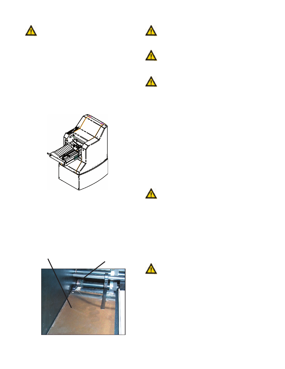
4.2 Transfer Table Mounting
Before mounting the transfer table into the first unit,
mount the 35T gear (FK0000824) from the accessory kit, on
the lower slitter shaft. Gear to be located with the hub against
the bearing race on the left hand side of the folder and
tighten the two set screws. (Guard removed for clarification)
See Figure 4.2-1.
Figure 4.2-1
Gear 35T
Transfer Table
WARNING
Do not operate machine without transfer table
drive gear guard installed on feed table.
WARNING
Do not reach into knife/slitter shaft area while
machine is running.