Multi-compartment walk-ins, Shear plates, Batten strips – Bally Refrigerated Boxes Modular Buildings User Manual
Page 5: Interior steel
REV: 1/2013
Instruction Manual IM-238-94 2013 © Bally Refrigerated Boxes, Inc. 5
9. Multi-Compartment Walk-Ins
A. The most common arrangement for a Walk-In is a two compartment
Cooler/Freezer combination. Installation of panels in this situation is the same as
described above. The use of a “Breaker” or “Tee” panel is used to separate the
different compartments. These panels will be either 23” or 46”; typically the
verticals are the opposite of the ceilings and floors.
B. The Partition Wall will have at least two special panels referred to as P-1 and P-2.
The panel widths are either 7.6” or 9.1” and are marked with a special blue sticker
that corresponds to the drawing. The P-2 panels are double tongued (hook
pockets on both sides) which allows for final locking of the partition wall.
C. In large multi-compartment Walk-Ins, (three compartments or more) it is very
important to control the alignment of the panels and make sure if there is any
growth in the vertical panels that they are growing at the same rate as the
ceiling and floors. A quick and accurate way to check for correct alignment is to
measure the distance from the edge of the ceiling to the nearest vertical panel
joint. This measurement must be 11½”; it must be maintained at every joint to
assure proper assembly of the Walk-In. In these instances we recommend that
after the floors are placed and leveled that the center most partition be the
starting point and to work toward either end of the box.
D. Look at the plan view and take special note of which side of the panels the
wrench hold are on.
If there is not a door in the partition wall the panels will lock to ceiling and floors in
either orientation. An error on the partition wall could cost many man hours to
correct. The entire box will most likely have to be taken down to correct this error
because condensation will occur. As a general rule of thumb, the wrench holes
should always be on the colder compartment side, usually the freezer.
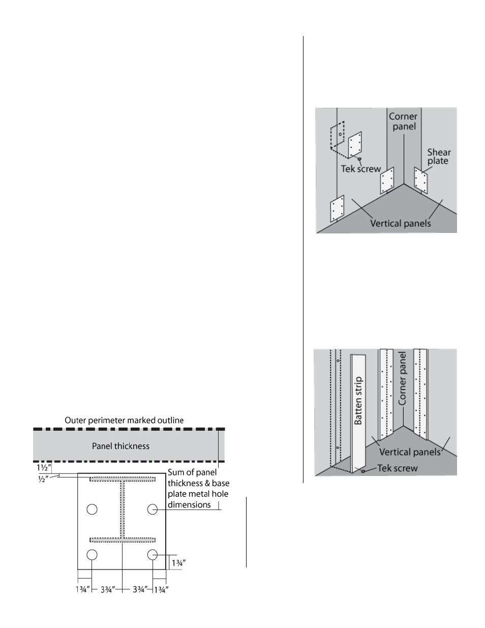
11. Shear Plates
Shear plate locations are described on the
plan view of the Modular Building. Shear
plates are installed over Speed-Lok locations
using 6 self-drilling Tekscrews provided by
Bally.
12. Batten Strips
Batten strip locations are described on the
plan view of the Modular Building. Batten
Strips are installed over vertical and/or
ceiling joints. Batten Strips are to cut length
and installed using Tekscrews provided by
Bally. Tekscrew centers should be
approximately 2" from ends and 8" center to
center.
10. Interior Steel
A. Interior steel framework is assembled before Modular Building assembly. Details
and layouts for interior steel are given on the plan view. Steel pieces are painted
primer and are numbered for identification.
B. Mark the exact outside perimeter as previously described. Check that outline is
square. See Section 3.
C. Using the plan view and base plate details, mark the positions of centerlines in
relation to perimeter. Once base plate locations are anchor bolt locations can be
determined using base plate details. See Figure 9.
D. If the floor surface is considerably uneven, find the highest point of steel column
positions and level all other columns to this height using leveling grout or plates
(Supplied by installer).
Note: Depending on architectural specifications, J-bolts can be
foamed into concrete when slab is poured or anchor bolts after
concrete slab is cured. Place all columns into position and
secure them to concrete slab. Plumb columns and position
lateral steel. Install lateral steel as shown on plan view details.
When ceiling panels are assembled, install provided self-drilling
Tekscrews through RA-1 tabs to secure to interior steel.