Audio Developments AD255 User Manual
Page 21
20
This module controls the level of main and monitor output signals and metering of the
output and monitor signals (including PFL). Calibration is achieved when the output
faders (5) are at maximum.
The two LCD meters read the various outputs and battery status. The upper meter (1)
reads left and right outputs; the upper bar reading left output and the lower right
output. The lower meter (2) reads the auxiliary outputs, channel output and battery
status. The upper bar reads auxiliary 1 output, the middle bar auxiliary 2 output and
the lower bar the channel signal level at the pre-fader point. This is activated when
PFL is selected on an input module. Battery status is read on the six segment bar in
the lower left corner. Beginning with the sixth bar, each bar goes out in turn as the
battery level falls.
When the internal or external voltage drops below a safe operating level, the first
segment of the battery level indicator will flash. Meters may be illuminated by ILL (6).
If a greater level of back-light is required then a facility exists on each meter, via a DIL
switch, to achieve this. Refer ADJUSTMENTS & CALIBRATION section.
The main output signal is metered and monitored after the output faders and limiters.
A pair of limiters may be switched in to the main output - LIM (10) - and linked for
stereo operation - LINK (7). LEDs (8) indicate when limiting is taking place. A choice
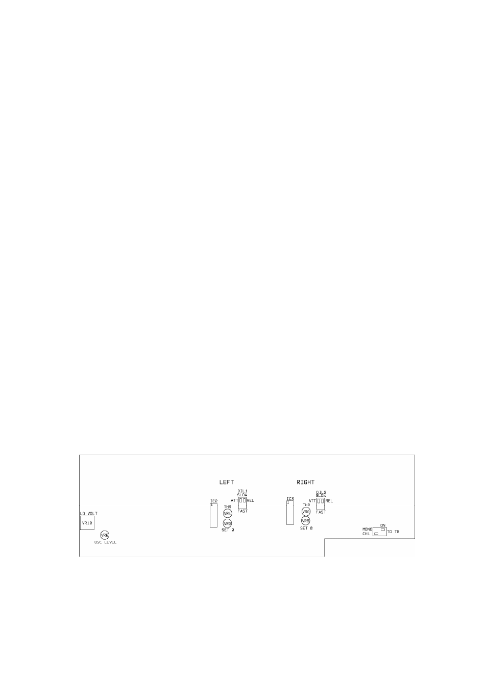
of fast or slow attack and release times may be made via the two DIL switches on the
output printed circuit board. When the limiters are being used as a stereo pair, they
should have their attack times and release times set identically. The factory setting for
the DIL switches is SLOW.
OUTPUT MODULE PRINTED CIRCUIT BOARD