Audio Developments AD255 User Manual
Page 16
15
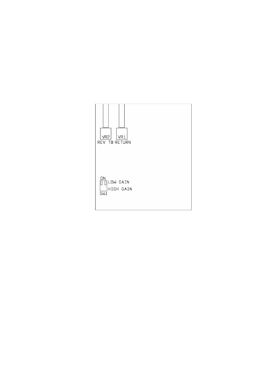
Thus, a two-way conversation can take place between mixer and boom operator with
the boom operator being able to listen to programme when no communication is
taking place. The programme may be selected, via a DIL switch; between the mono
output from the mixer or the signal from input channel 1 (when being used for the
boom microphone). The DIL switch appears on the output module PCB. (Refer to
block diagram and line drawing in output section.) The mixer leaves the factory with
the DIL switch set in the MONO position.
A three-position rocker switch BATT/EXT (7) selects either internal batteries or an
external DC source. Power to the mixer is confirmed by the MIX ON LED on the
output module. The LED flashes when the internal voltage falls below the safe
operating level of 9V.
External powering of the mixer is via a 4-pin XLR (6).
XLR
Pin 1
OV
Pin 3
NC
Pin 2
Charge
Pin 4
12-15V DC
A suitable external power supply unit is model number AEH24US15 supplied by Audio
Developments (Part No 94-100-015), but any external DC source must be capable of
delivering 1A at 12V.