Initial setup – Wilson Manifolds 810100 Progressive Nitrous Controller and Vehicle Data Logger User Manual
Page 15
Nitrous Pro-Flow, 4700 NE 11
th
St., Ft. Lauderdale, FL 33334 Pro-Flow Part. No. 810100
(954) 771-6216
www.nitrousproflow.com
1/2008
Page 15
GPI – input level on the GPIO displayed as a
digital (on/off) signal. On means that the GPIO is
grounded
GPO – output status on the GPIO displayed as a
digital (on/off) signal. On means that the GPIO is
grounded
STAGE 1 TRIG, STAGE 2 TRIG – stage output
status displayed as a digital (on/off) signal. On
status indicates that all trigger conditions are
met and the outputs are on
STAGE 1 PWM, STAGE 2 PWM – percent
PWM
Additional data is displayed at the lower right
side of the screen. This data includes:
Controller Status – general nitrous controller
status
Log Interval – the actual data logging interval in
seconds
The nitrous controller data buffer stores the last
2700 data points. With a nominal data logging interval
of 0.10 seconds, this corresponds to 4.5 minutes of
data. You can set the data logging interval by means of
the PC Link Nitrous software.
You can clear the data within the nitrous
controller by using the Clear Data Buffer command
from the Communications menu. If you change the
data logging interval, you should also clear the data
buffer.
INITIAL SETUP
1. Make sure that your nitrous bottle valve is shut.
Remove the 50 amp maxi-fuse(s) supplying power
to the solenoids.
2. Connect the USB cable, start PC Link Nitrous
software, and open the sample.dat setup file.
3. Refer to page 7 for RPM Pulses/Rev setting. Enter
the setting corresponding to your application and
upload to the nitrous controller. If you are not using
the RPM input, use the default value and skip to
step 7.
4. Start the engine and turn on the arming switch.
The status LED should illuminate (if not, recheck
all electrical connections). Start Nitrous Log
software and use the View Real Time Data
command from the View menu. Verify correct
engine RPM display (should display idle RPM
value same as vehicle tachometer).
5. If the RPM display is incorrect (too high or too low)
but not zero, you will need to change the RPM
Pulses/Rev setting. Turn off the ignition switch in
between tests. If the RPM display is too low, use a
lower RPM Pulses/Rev setting. If the RPM display
is too high, use a higher RPM Pulses/Rev Setting.
Change the setting as required in PC Link Nitrous
and upload to the nitrous controller.
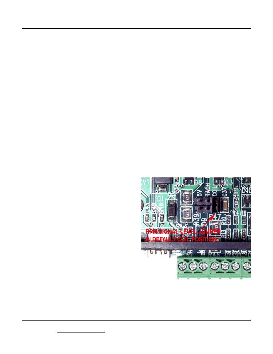
6. If the RPM display is zero, you may need to
change the RPM signal level jumper on the nitrous
controller printed circuit board (PCB). Turn off the
ignition switch in between tests. Remove the top
cover of the housing and refer to Figure 13. The
jumper has three positions labeled 5V, TACH, and
COIL. The default factory setting is in the COIL
position (for a high voltage coil signal). Move the
jumper to the TACH position (for a 12V tach
signal) and repeat the test. If the RPM display is
still zero and your engine has coil-on-plug ignition,
move the jumper to the 5V position (for a logic
level signal). Do not attempt to use the 5V
position for any other type of ignition system. If
the RPM display is still zero, call tech support.
Reinstall the cover. If required, go back to step 5 to
establish the correct RPM Pulses/Rev setting.
Figure 13 – RPM Signal Level Jumper
7. Turn on the ignition key, but do not start the
engine. In the Nitrous Log software, use the Real
Time Display Options command from the Edit
menu and select Analog (0-5V) Throttle Position
(TPS) display. Then go back to View Real Time
Data. Write down the voltage levels for zero