Weidmuller G418 Ultra SlimPak User Manual
Page 3
A major advantage of the G418 is its wide ranging capabilities and ease of configuration. The G418 has 16
input temperature range settings, six RTD type settings and five output range settings. Trim potentiometers
allow 50% input zero and span adjustability within each of the 16 full scale input ranges.
Unless otherwise specified, the factory presets the Model G418 as follows:
Input: Pt100
M
Range: -200 to 600°C
Output: 4-20mA
The DC power input accepts any DC source between 9 and 30V; typically a 12V or 24VDC source is used.
In order to minimize interference from electrical and magnetic fields the use of shielded and twisted-pairs is
recommended for the input and output. For other I/O ranges, refer to Tables 1 through 6 and reconfigure
switches SW1, SW2 and SW3 for the desired input type, range and output.
Do not attempt to change any switch settings with power applied. Severe damage will result!
1. Choose the desired temperature range from table 1 or 2 depending on RTD type.
2. With DC power off, position input switches 1 through 5 on "SW2" for the desired temperature range
(Table 3).
3. Set position 6 through 8 of input range switch "SW2" for the desired RTD type (Table 4).
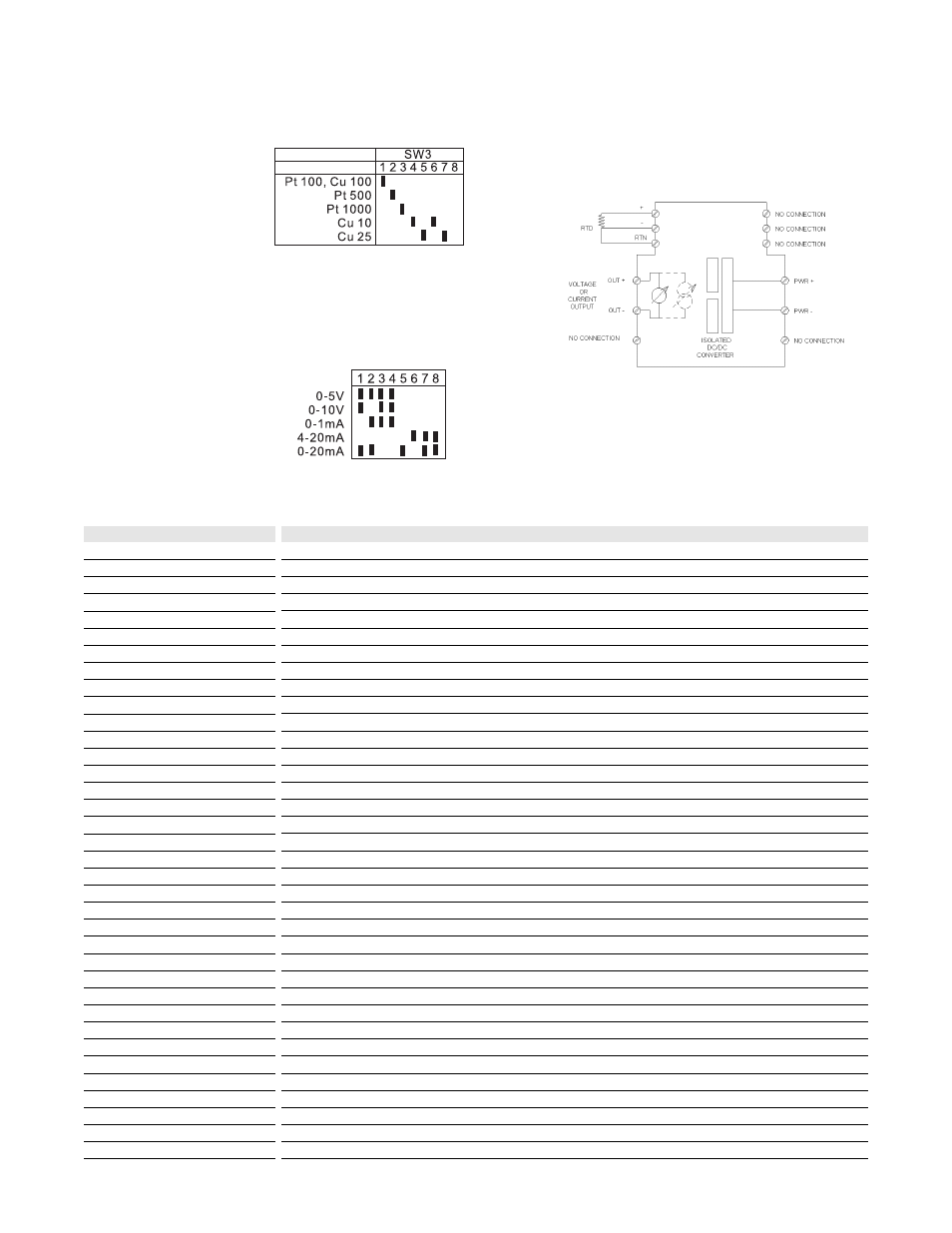
4. Set position 1 through 8 of excitation switch "SW3" for the desired RTD type (Table 5).
5. Set position 1 through 8 of output range switch "SW1" for the desired output signal (Table 6).
1. After configuring the dip switches, connect the input to a calibrated RTD source or decade resistance
box. Connect the output to the actual device load (or a load approximately equivalent to the actual device
load value) and apply power.
Note: To maximize thermal stability, final calibration should be performed in the operating installation,
allowing approximately 1 to 2 hours for warm up and thermal equilibrium of the system.
2. Set the calibrator to the desired minimum temperature and adjust the zero potentiometer for the
desired minimum output.
3. Set the calibrator to the desired maximum temperature and adjust the span potentiometer for the desired
maximum output.
4. Repeat steps 2 and 3, as necessary for best accuracy.
Configuration
WARNING:
Calibration
Table 5:
Excitation type switch settings
(SW3 - 1 through 8)
Table 6:
Output switch settings
(SW1 - 1 through 8)
Key:
n ON