Weidmuller G118 Ultra SlimPak User Manual
Page 3
Unless otherwise specified, the factory presets the Model G118 as follows:
Input: Platinum (100
M)
Range: 0 to 250°C
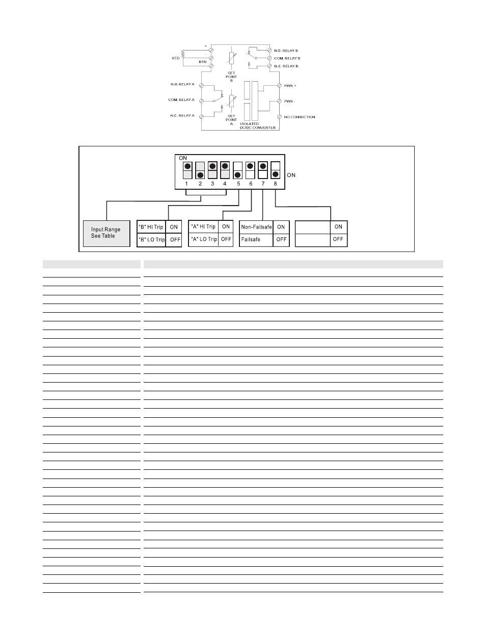
Output: Dual, SPDT
Trip: A:HI, B:LO
Failsafe: No
Deadband: A, B: 1.0%
The DC power input accepts any DC source between 9 and 30V; typically a 12V or 24Vdc source is used.
For other I/O ranges, refer to Tables 1 through 3 and reconfigure switches SW1 and SW2
for the desired input type, range and function.
Do not attempt to change any switch settings with power ap-plied. Severe damage will result!
Input
1. With DC power off, position input switches 1 through 6 on "SW2" for RTD type (see Table 1).
2. Set position 1 through position 4 of input range switch "SW1" for the desired RTD type and input
temperature range (Table 3).
3. Set position 5 and 6 of input range switch "SW1" to ON for a HI trip setpoint or OFF for a LO trip
setpoint (Figure 4).
4. Set position 7 of input range switch "SW1" to ON for non-failsafe operation or OFF for failsafe operation
(e.g. alarm trips upon power failure).
1. After configuring the DIP switches, connect the input to a calibrated RTD source or a resistance decade
box and apply power. See wiring diagram.
NOTE: To maximize thermal stability, final calibration should be performed in the operating installation,
allowing approximately 1 to 2 hours for warm up and thermal equilibrium of the system.
2. Setpoint Calibration: Before adjusting the setpoint, adjust deadband pot to its minimum (20 turns counter
clockwise). With the desired trip RTD resistance input applied, adjust setpoint pot until the relay trips. For
HI trip calibration, start with the set-point pot above the desired trip (20 turns clockwise). For LO trip
calibration, start with the setpoint pot below the desired trip (20 turns counter clockwise).
3. Deadband Calibration: Set dead-band pot to its minimum (20 turns counter clockwise). Adjust the
setpoint pot to desired trip. Adjust RTD resistance input until relay trips. Re-adjust deadband pots to 5%
(20 turns clockwise). Set RTD resistance input to desired deadband position. Slowly adjust deadband
(counter clockwise) until relay untrips.
When switching inductive loads, maximum relay life and transient EMI suppression is achieved using
external protection (see Figures 2 and 3). Place all protection devices directly across the load and
minimize all lead lengths. For AC inductive loads, place a properly rated MOV across the load in parallel with
a series RC snubber. Use a 0.01 to 0.1
HF pulse film capacitor (foil polypropylene recommended) of
sufficient voltage, and a 47
M, 1/2W carbon resistor. For DC inductive loads, place a diode across the load
(PRV>DC supply, 1N4006 recommended) with (+) to cathode and (-) to anode (the RC snubber is an
optional enhancement).
Configuration
WARNING:
Calibration
Relay Protection and EMI
Suppression
3
Not Used
Not Used
Figure 4
G118 input
range/function
selection (SW1)
Factory default
settings