0 advanced modifications – Vicor Half-chip PRM-RS Customer Board User Manual
Page 16
UG:008
vicorpower.com
Applications Engineering: 800 927.9474
Page 16
10.0 Advanced Modifications
10.1 Stability, Bandwidth and Transient Response
The nominal compensation of the half-chip PRM-RS Customer Board is set to provide relatively low
bandwidth in order to ensure stability under all of the recommended configurations. The closed
loop frequency response varies as a function of line, load, trim, and output capacitance. Refer to
the PRM
®
data sheet for a detailed description and AC model. Adding additional capacitance to the
output of the PRM or VTM
®
Customer Board may result in instability. When testing transient
response, it is important for the user to understand that response is a function of compensation
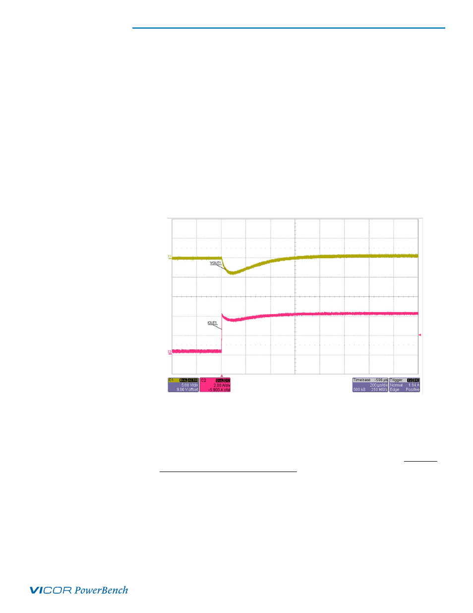
which should be optimized based on the end requirements for best performance. An example
transient response waveform, taken with a passive resistive load, is shown below. As illustrated, the
recovery time is on the order of 400
µsec. It should be noted that with control loop optimization,
faster transient response recovery times are possible.
10.1.1 Compensation Adjustment
The sense and compensation circuit is shown below. Refer to the BOM (4.3) for component
values. If higher bandwidth, faster transient response, and/or operation outside of the
recommended configurations are desired, the user may adjust the compensation, referring to
the appropriate PRM data sheet for guidelines. This type of tuning is highly recommended and
generally requires the use of a network analyzer to measure the closed loop response. Stability
must be verified across all line, load, and trim conditions. Typically maximum crossover
frequency will occur at full load, and minimum crossover frequency will occur at minimum load.
Examples of closed loop response plots are illustrated below.
Figure 13: Example
PRD48BH480T200A00
(VIP0100THJ-CB) transient response
PRD48BH480T200A00 +
V048F480T006-CB, Remote Sense
Configuration