Vicor PI2127-EVAL1 60V/12A Full-Function High Side Active ORing Evaluation Board User Manual
Page 5
Picor Corporation •
picorpower.com
PI2127-EVAL1 User Guide
Rev. 1.0
Page
5 of 9
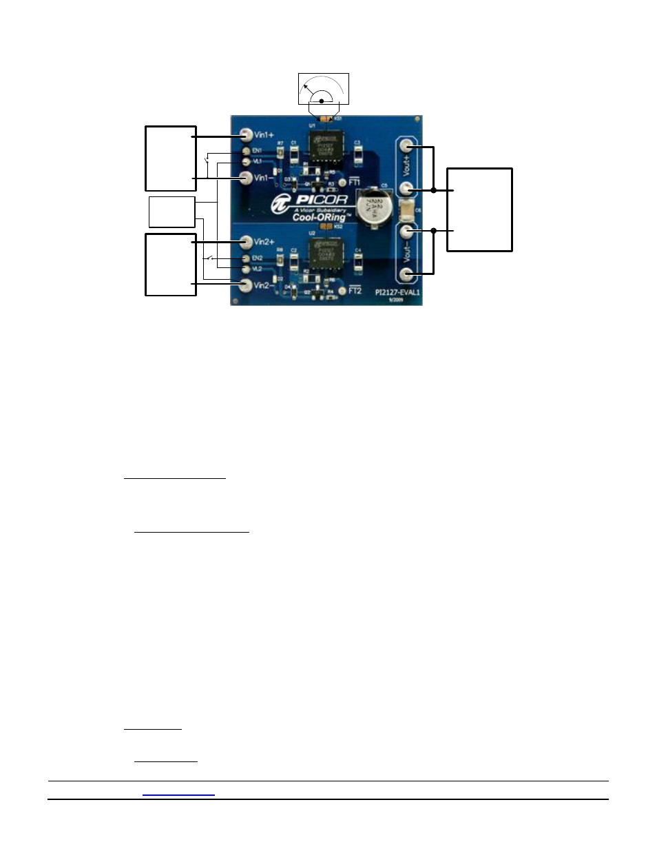
Figure 3: Layout configuration for typical redundant power application, using PI2127-01-LGIZ
3.2. If R
PG
is desired instead of the Constant Current
bias circuit, remove the Constant Current bias
circuit components from the evaluation board.
The upper ORing (U1) constant current bias
circuit components are Q1, R3, R7 and D3. The
lower ORing (U2) constant current bias circuit
components are Q2, R4, R8 and D4. R
PG
value
can using the following equations:
And R
PG
maximum power dissipation is:
Where:
:
Minimum applied input voltage (Vin to
Rtn)
:
Maximum applied input voltage (Vin to
Rtn)
: Controller maximum clamp voltage,
12.5V
: Controller minimum clamp voltage, 11V
:
Controller maximum bias current, use
2.0mA
R
PG
calculation example
Vin (minimum) = 40V and Vin (maximum) = 50V
4. Hook Up of the Evaluation Board
4.1. Connect the positive terminal of PS1 power
supply to Vin1+. Connect the ground terminal of
PS1 to Vin1-. Set the power supply to 48V. Keep
PS1 output disabled, off.
4.2. Connect the positive terminal of PS2 power
supply to Vin2+. Connect the ground terminal of
PS2 to Vin2-. Set the power supply to 48V. Keep
PS2 output disabled, off.
4.3. Connect the logic power supply PS3 positive
terminal to VL1 and VL2. Connect the ground
terminal of this power supply to either Vin1- or
Vin2-. Set the power supply to the desired logic
voltage level, 3.3V or 5V. Keep PS3 output
disabled, off.
4.4. Connect the electronic load to the output
between Vout+ and Vout-. Set the load current
to 5A.
4.5. Enable (turn on) PS3 power supply output.
4.6. Enable (turn on) PS1 power supply output.
4.7. Turn on the electronic load.
4.8. Verify that Vout+ voltage is a few millivolts
below 48V. This verifies that the PI2127 (U1)
internal MOSFET is in conduction mode.
4.9. Verify that Vin2+ is low. This verifies that the
PI2127 (U2) internal MOSFET is off.
DC
Electronic
Load
PS1
-
PS2
+
-
+
-
0-60V/15A
25A
R
DS(on)
V
S1 D1
0-60V/15A
PS3
+
-
12V/100mA
Logic PS
+
S2 D2