Bill of material – Vicor PI2007-EVAL2 12V/15A High Side Active ORing Evaluation Board User Manual
Page 4
Picor Corporation • picorpower.com
PI2007-EVAL2 User Guide Rev. 1.1 Page
4 of 9
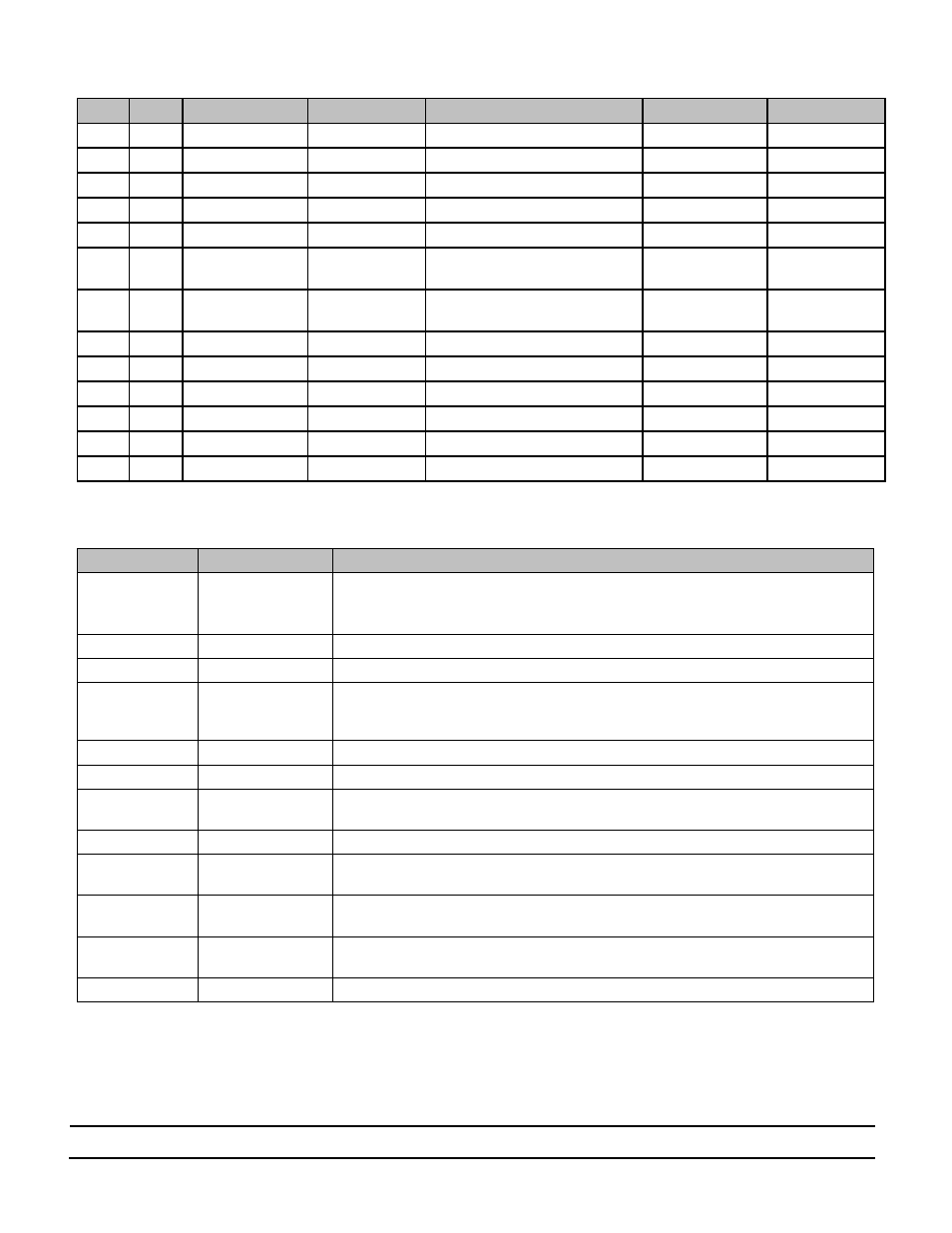
Bill of Material
Item
QTY
Ref. Designator
Value/Part NO.
Description
Footprint
Manufacturer
1
2
C1, C2, C3, C4
Not Installed
MLCC Capacitor, X7R, 1uF,50V
1206
2
2
C5, C6
1μF
MLCC Capacitor, X7R, 1uF,50V,
805
3
1
C7
22μF
Electrolytic Capacitor, 22uF,100V
Panasonic _E/F
Panasonic
4
1
C8
Not Installed
MLCC Capacitor, 10uF,25V
1812
5
2
D1, D2
LTST-C191CKT
LED, Red
0603 LED
Lite-On
6
6
1,
2, VC1,
VC2, VL1, VL2
1528
Turret Test point
TURRET - 1528
Keystone
Electronics
7
6
Rtn, Rtn, Rtn, Vin1,
Vin2, Vout
1502
Turret Test point
TURRET - 1502
Keystone
Electronics
8
2
Q1, Q2
SI4630DY-T1-GE3
N-MOSFET,25V,40A
PPAK SO-8
Siliconix
9
1
R1, R2
0Ω
Resistor,0 Ω,1%,0.1W
0603
10
1
R3, R4
430Ω
Resistor,430Ω, 1%, 0.125W
0805
11
1
R5, R6, R7, R8
Not Installed
12
2
R9, R10
1.5K
Resistor,1.5K,1%,0.1W
603
13
2
U1, U2
PI2007-00-QEIG
Picor Cool ORing Controller IC
3x3mm 10L TDFN
PICOR
Table 2: PI2007-EVAL2 Evaluation Board Bill of Materials
Ref. Designator
Value/Part NO.
Functional Description
C1, C2, C3, C4
Not Installed
Snubber to reduce voltage ringing when the device turns off
Add the capacitors if a long harnesses are used to connect the power source or load to the
board.
C5, C6
1uF
VC Bypass Capacitor
C7
22uF
Output (Load) Capacitor
C8
Not Installed
Output (Load) Capacitor, this capacitor can be installed if instead of C7 if the user requires a
ceramic load capacitor, 1812 package can accommodate a high ceramic capacitors value at
25V rating.
D1, D2
LTST-C191CKT
To indicate a fault exists when it is on
Q1, Q2
SI4630DY-T1-GE3
ORing switch
R1, R2
0Ω
Gate resistor, optional to slow gate turn off time, higher value resistor will reduce gate pull
down peak current
R3, R4
430Ω
VC bias resistor
R5, R6,
Not Installed
Optional to use PI2007 external VC bias voltage, removing R3 and R4 when external bias
voltage is used.
R7, R8
Not Installed
Optional to use PI2007 internal VC bias resistor (VR) by placing 0Ω resistor and removing R3
and R4
R15, R16
1.5K
LED current limit resistor, selected to operate at 3.3V and 5.0V logic voltage. Replace R15
and R16 with the proper resistor value for different logic voltage.
U1, U2
PI2007
Cool ORing Controller
Table 3: Component functional description